HANDLING LIGHT AIRCRAFT
CONTENTS
Introduction
List of figures
1
BASIC THEORY OF FLIGHT
2
THE AIRCRAFT
2.1
THE AIRFRAME
2.1.1 The wing
2.1.2 The tailplane and
elevator
2.1.3 The fin and rudder
2.1.4 The fuselage
2.1.5 The landing gear
2.1.6 Trim tabs
2.1.7 The cabin
2.1.8 Other components
2.2
THE ENGINE
2.2.1 Combustion
2.2.2 Behaviour of
liquids and gases
2.2.3 The four-stroke
cycle
2.2.4 The carburettor
2.2.5 The throttle
2.2.6 Mixture strength
and mixture control
2.2.7 Carburettor heat
control
2.2.8 Detonation
2.2.9 Fuel injection
2.2.10
The ignition system: the magneto
2.2.10.1 Mechanical
generation of electricity
2.2.10.2 Conversion to
high voltage
2.2.10.3 Timing and
distribution
2.2.10.4 The spark plug
2.2.10.5 Dual ignition
systems
2.2.10.6 The impulse
magneto
2.2.10.7 Ignition control
2.2.10.8 Electronic
ignition systems
2.2.11
The oil system
2.2.11.1 Oil quantity
and consumption
2.2.11.2 Oil grade
2.2.11.3 Dry-sump systems
2.2.12 Engine cooling
2.2.13 The propeller
2.2.14 Engine mounting
2.2.15 The cowling
2.2.16 The tachometer
2.2.17 Engine-driven
systems
2.2.18
FADEC systems
2.3
THE FUEL SYSTEM
2.3.1 Fuel quantity and
consumption
2.3.2 Fuel grade
2.4
THE ELECTRICAL SYSTEM
2.4.1 The alternator
2.4.2 The electrical
circuit
2.4.3 The electrical
system
2.4.4 Fuses and
circuit-breakers
2.4.4.1 The fuse
2.4.4.2 The
circuit-breaker
2.4.5 Electric motors
2.4.6 The ammeter
2.4.7 Electrical services
2.5
THE HYDRAULIC SYSTEM
2.5.1 The brake system
2.5.2 Hydraulic fluid
2.5.3
Hydraulically-operated landing gear retraction
2.6
THE FLIGHT INSTRUMENTS
2.6.1 Visual flight
2.6.2 Instrument flight
2.6.3 The International
Standard Atmosphere
2.6.4
The airspeed
indicator
2.6.4.1 Pressure error
and instrument error
2.6.4.2 Density error
2.6.4.3 Groundspeed
2.6.5
The altimeter
2.6.5.1 Pressure
datum setting
2.6.5.2 Altimeter
terminology
2.6.5.3 Barometric error
2.6.5.4 Terrain clearance
2.6.5.5 Temperature error
2.6.5.6 Pressure error
and instrument error
2.6.5.7 GPS derived
altimetry
2.6.6
The vertical speed
indicator
2.6.6.1 Lag
2.6.6.2 Pressure error
2.6.7 Direction
2.6.8
The magnetic compass
2.6.8.1 Compass errors
2.6.9 The gyroscope
2.6.9.1 The
suction-driven gyro
2.6.9.2 The
electrically-driven gyro
2.6.9.3 Flight
instrument power supplies
2.6.10
The attitude
indicator
2.6.11
The direction
indicator
2.6.11.1 DI errors
2.6.11.2 The
self-synchronising DI
2.6.12 Toppling
2.6.13
The
turn-and-balance indicator
2.6.13.1 The turn
indicator
2.6.13.2 The balance
indicator
2.6.14 Electronic flight
instrument systems (EFIS)
2.7
THE PILOT'S CONTROLS
2.7.1 The flight controls
2.7.1.1 The ailerons
2.7.1.2 The elevators
2.7.1.3 The rudder
2.7.1.4 Control locks
2.7.2 The flaps
2.7.3 The elevator trim
tab
2.7.4 The engine controls
2.7.5 Electrical services
2.7.6 Seats and harnesses
2.8
AVIONICS
2.8.1 The COM radio
2.8.2 The transponder
2.8.3 The GPS map display
2.9
THE CHECKLIST
3
DETAILED THEORY OF FLIGHT
3.1
WEIGHT AND CENTRE OF GRAVITY
3.2
LIFT
3.2.1 Angle of attack
3.2.2 Wing shape
3.2.3 Factors affecting
lift
3.2.3.1 Angle of attack
3.2.3.2 Speed
3.2.3.3 Aerofoil shape
3.2.3.4 Wing area
3.2.3.5 Air density
3.3
TAIL DOWN-FORCE
3.4
DRAG
3.4.1 Factors affecting
drag
3.4.1.1 Object shape
3.4.1.2 Speed
3.4.1.3 Object size
3.4.1.4 Air density
3.4.2 Wing
drag
3.4.2.1 Speed
3.4.2.2 Angle of attack
3.4.2.3 Wing planform
3.4.2.4 Air density
3.4.3 Total aircraft drag
3.5
ANGLE OF INCIDENCE
3.6
WING EFFICIENCY
3.7
THE MOTION OF THE AIRCRAFT
3.8
STABILITY
3.8.1 Longitudinal
stability
3.8.2 Directional
stability
3.8.3 Lateral stability
3.8.4 Interaction of
directional and lateral stabilities
3.8.5
Effect of position of centre of
gravity on stability
3.8.5.1 Effect on
longitudinal stability
3.8.5.2 Effect on
directional stability
3.8.5.3 Effect on
lateral stability
3.9
AIR DENSITY
3.10
THRUST: THE PROPELLER
3.10.1 Effect of varying
engine power setting
3.10.2 Effect of speed
on RPM
3.10.3 Windmilling
3.10.4 Propeller
efficiency
3.10.4.1 Effect of speed
on propeller efficiency
4
AIRCRAFT HANDLING
4.1
AIRFRAME LIMITATIONS
4.2
ENGINE HANDLING AND OPERATING LIMITATIONS
4.2.1 Control of power
4.2.2 Use of mixture
control
4.2.3 Engine operating
limitations
4.3
PICKETING AND USE OF CHOCKS
4.4
MANHANDLING AND POSITIONING THE AIRCRAFT FOR ENGINE-STARTING
4.5
PROPELLER HANDLING
4.6
AIRCRAFT INSPECTION
4.7
ENGINE STARTING
4.8
TAXYING
4.8.1 Brake failure
4.9
ENGINE TESTING
4.10
PRE-TAKE-OFF CHECKS
4.10.1 Airframe
4.10.2 Engine
4.10.3 Instruments
4.10.4 Electrical
services
4.11
PROCEDURE
AFTER LANDING
4.12
EFFECT OF
FLIGHT CONTROLS IN FLIGHT
4.12.1 Effect of
elevators
4.12.2 Effect of ailerons
4.12.2.1 Consequence of
bank
4.12.3 Effect of rudder
4.12.3.1 Consequence of
yaw
4.12.3.2
Propwash-induced yaw
4.13
EFFECT OF
VARYING PROPWASH STRENGTH
4.14
EFFECT OF
VARYING AIRSPEED ON FLIGHT CONTROLS
4.15
EFFECT OF
VARYING CONTROL MOVEMENT
4.16
EFFECT OF
FLIGHT CONTROLS IN DISPLACED ATTITUDE
4.17 FUNCTION
OF FLIGHT CONTROLS
4.17.1 Function of
elevators
4.17.2 Function of
ailerons
4.17.3 Balance: function
of rudder
4.18
FUNCTION
OF TRIM TABS
4.18.1 Trimming technique
4.18.2 Trim changes
4.19
THE FLIGHT
PATH: THE THIRD DIMENSION
4.20
STRAIGHT
AND LEVEL FLIGHT
4.20.1 Level flight
4.20.2 Control of flight
path with attitude
4.20.3 Control of speed
with power
4.20.4 Straight flight
4.20.5 Balance
4.20.6 Drag
4.20.7 Power
4.20.8
Flying for maximum
range
4.20.8.1 Effect
of height on range
4.20.9
Flying for maximum
endurance
4.20.9.1 Effect
of height on endurance
4.20.10 Technique for
straight and level flight
4.20.11 Correction of
deviations
4.21
CLIMBING
4.21.1 Climbing at
maximum rate
4.21.2 Climbing at
maximum gradient
4.21.3 Summary of
techniques for climbing
4.21.4 Cruise climb
4.22
DESCENDING
4.22.1 Gliding at
minimum gradient of descent
4.22.2 Sideslipping
4.22.3 Powered descent
4.22.4 Summary of
techniques for descending
4.22.5 Cruise descent
4.23
FLAPS
4.23.1 Effect of flaps
on stalling speed
4.23.2 Effect of flaps
on trim
4.23.3 Control of speed
and vertical flight path
4.23.4 Effect of flaps
on forward view from cabin
4.23.5 Use of flaps for
take-off
4.23.6 Use of flaps for
approach and landing
4.24
MEDIUM
TURNS
4.24.1 Level turns
4.24.1.1 Balance: use of
rudder
4.24.1.2 Rate of turn
4.24.2 Climbing turns
4.24.3 Descending turns
4.24.4 Increase of
stalling speed
4.24.5 Summary of
techniques for turning
4.25
STALLING
AND SPINNING
4.25.1 Symptoms of
impending stall
4.25.2 The stall
4.25.3 The spin
4.25.4
Recovery from the
stall
4.25.5 Practising stalls
4.25.5.1 Entering the
stall from straight and level flight
4.25.5.2 Effect of
lowered flaps on stalling characteristics
4.25.5.3 Effect of power
on stalling characteristics
4.25.5.4 Entering the
stall from level turning flight
4.25.5.5 Stalling in
climbing and descending flight
4.25.5.6 Stalling in
pitch-up manoeuvres
4.25.6 Effect of loaded
weight on stalling speed
4.25.7 Effect of CG
position on stalling characteristics
4.25.8
Inadvertent
stalls: recovery at the incipient stage
4.25.9
Recovery from the
spin
4.25.10 Recovery from
spiral dive
4.25.11 Practising spins
4.25.11.1 Entering the
spin
4.25.12 Effect of CG
position on spinning characteristics
4.25.13 Airframe stress
during spin recovery
4.25.14
Inadvertent spins
4.25.15
Stall and spin
avoidance
4.26
THE RUNWAY
4.27
THE CIRCUIT
4.28
THE
TAKE-OFF
4.28.1 Normal take-off
technique (flaps up)
4.28.1.1 Wind
4.28.2 Crosswind take-off
4.28.2.1 Crosswind
component
4.28.3 Short take-off
4.28.4 Obstacle
clearance after take-off
4.28.5 Rejected take-off
4.29
FLYING THE
CIRCUIT
4.30
THE
APPROACH
4.30.1 Base leg
4.30.2 Final approach
4.30.2.1 Approach path
control
4.30.2.2 Centre-line
tracking
4.30.2.3 Alternative
technique for final approach
4.31
THE LANDING
4.31.1 Normal landing
technique
4.31.1.1 Control wheel
movement
4.31.1.2 Centre-line
tracking
4.31.1.3 Wind
4.31.2 Crosswind landing
4.31.2.1 Crab method for
crosswind landings
4.31.2.2 Crossed
controls
(sideslip) method for crosswind landings
4.31.3 Crosswind
component
4.31.4 Short landing
4.32
GLIDE
APPROACH AND LANDING
4.32.1 Glide approach
technique
4.32.2 Mis-judged
approaches
4.32.3 The flare
4.33
FLAPLESS
APPROACH AND LANDING
4.33.1 The
flare and landing
4.34
THE
GO-AROUND
4.35
THE
WINDSOCK
4.36
STEEP TURNS
4.36.1 Lift increase
4.36.2 Rate of turn
4.36.3 Increase of
stalling speed
4.36.4 Steep level turns
4.36.4.1 Stall avoidance
4.36.4.2 Recovery from
spiral dive
4.36.4.3 Maximum rate
turns
4.36.5 Steep
gliding turns
4.37
REVIEW OF
CONTROL FUNCTIONS
4.37.1 Function of
elevators
4.37.2 Function of
ailerons
4.37.3 Function of rudder
4.37.4 Function of power
4.37.5 Flight near
stalling regime
4.38
INSTRUMENT
FLIGHT
4.38.1 Physiological
aspects
4.38.2 Instrument
scan
4.38.3 Control
technique
4.38.4 Navigation
4.38.5 Terrain clearance
4.38.6 Collision
avoidance
4.38.7 Meteorological
aspects
4.39
CONSTANT-SPEED PROPELLERS
4.39.1 Theoretical
considerations
4.39.2 Technical
description
4.39.3 The
manifold pressure indicator
4.39.4 Operating
technique
4.40
RETRACTABLE LANDING GEAR
5
EMERGENCY HANDLING
5.1
ENGINE FAILURE
5.1.1 Forced landing
procedure
5.1.1.1 Choice
of most suitable field
5.1.1.2 Choice
of landing direction
5.1.1.3 Planning
descent path
5.1.1.4 Attempting
to rectify failure
5.1.1.5 Impact
checks
5.1.1.6 Flying
the descent path
5.1.1.7 Overrunning
5.1.1.8 Mis-judged
approaches
5.1.1.9 Summary of
forced landing procedure
5.1.1.10 After landing
5.1.1.11 Engine failure
at low height
5.1.1.12 Engine failure
after take-off
5.1.2 Further
considerations
5.1.3 Practising
forced landing procedure
5.2
THE PRECAUTIONARY LANDING
5.3
ENGINE FIRE
5.3.1 Engine
fire in the air
5.3.2 Engine
fire on the ground
5.4
CABIN FIRE
5.4.1 Further
considerations
5.5
DITCHING
5.6
LANDING GEAR EMERGENCIES
6
THE FLIGHT MANUAL
6.1
TECHNICAL DESCRIPTION
6.2
LIMITATIONS
6.3
PERFORMANCE
6.3.1 Length of
take-off run required
6.3.1.1 Wind component
6.3.1.2 Airfield
elevation
6.3.1.3 Air temperature
6.3.1.4 aircraft loaded
weight
6.3.1.5 Flap position
6.3.1.6 Gradient of
runway
6.3.1.7 Nature of runway
surface
6.3.1.8 Practical
considerations
6.3.2 Obstacle
clearance after take-off
6.4
LOADING
6.4.1 Empty weight and
loaded weight
6.4.2 CG position
6.4.3 Practical
considerations
6.4.4 Dangers of
incorrect loading
Introduction
This book, written by a qualified flying instructor,
is intended to help student
pilots during their basic flight training
and to enable qualified pilots to refresh their knowledge. The areas
covered are the technical description of conventional all-metal light
aircraft including recent developments such as FADEC engine controls
and EFIS flight instrumentation, the theory of flight and aircraft
handling in daylight visual weather conditions (although a
brief dissertation on the fundamentals of instrument flight is also
included).
On
the subject
of personal
pronouns I have used the masculine 'he' form throughout to make the
text more easily readable, asking the reader to assume the inclusion of
the feminine
'she' form by inference. I hope this modus
scribendi
is
acceptable to
female readers.
List
of figures
1
BASIC THEORY OF
FLIGHT
1
The aircraft
2
Disposition of
forces acting on an aircraft in
flight at constant speed and height
3
High-winged
aircraft
2
THE AIRCRAFT
4
Left wing
5
Flap
movement
6
Aileron
movement
7
Left
tailplane and elevator
8
Elevator
movement
9
Fin and
rudder
10
Rudder movement
11
The fuselage
12
Landing gear unit
13
Oleo-pneumatic unit in
various situations
14
Creep marks
15
Adjustable elevator trim tab
16
Fixed aileron trim tab
17
Flow of gas through a
constriction
18
The cylinder and its
associated components (induction
stroke)
19
Compression stroke
20
Power stroke
21
Exhaust stroke
22
Horizontally-opposed
four-cylinder aero-engine
23
Float-type carburettor
24
Throttle valve
25
Mixture control at
intermediate position
26
Carburettor heat control
'on'
27
Mechanical generation of
electricity
28
The magneto: the electrical
set-up
29
The spark plug
30
Dual ignition system for
four-cylinder aero-engine
31
The magneto switch
32
The oil system
33
Cooling fins
34
The propeller
35
The tachometer
36
The fuel system
37
Electrical circuits
38
Aircraft electrical system
39
The fuse
40
Ammeter location
41
Ammeter presentation
42
Ammeter located in battery
circuit
43
Ammeter presentation
(battery circuit)
44
The brake system
45
Landing gear retraction
mechanism
46
The flight instruments
47
High and low attitudes
48
View from pilot's seat
49
Bank left and right (view
from behind)
50
View from pilot's seat
51
Aircraft in cruising flight
52
ASI working principle
53
Airspeed indicator
54
The pressure head
55
Airspeed indicator
presentation
56
TAS (knots) corresponding
to IAS of 100 knots
57
TAS and GS
58
The altimeter
59
Altimeter presentation
(showing 4650 feet)
60
Altimeter presentation
(showing 8800 feet)
61
Altimeter presentation
(showing 12000 feet)
62
Reference for height
measurement
63
Barometric error
64
Terrain clearance
65
The vertical speed indicator
66
Vertical speed indicator
presentation
67
Incorrect VSI indication
during abrupt transition from climb to descent
68
Magnetic variation
69
Magnetic direction
70
Heading
71
The magnetic compass
72
Magnetic compass showing
heading 270°M
73
Heading indications
74
The gyro
75
Suction-driven gyro
76
Attitude indicator gyro
erect
77
Attitude indicator
presentation
78
Attitude indicator
indications
79
Direction indicator gyro
erect
80
DI indicator indicating 360°
81
DI indicator indicating 255°
82
Turn indicator gyro
precession
83
Turn indicator presentation
84
Turn indications
85
Balance indicator
86
Unbalanced flight
87
Turn-and-balance indicator
88
EFIS display
89
Cabin layout
90
Aileron control
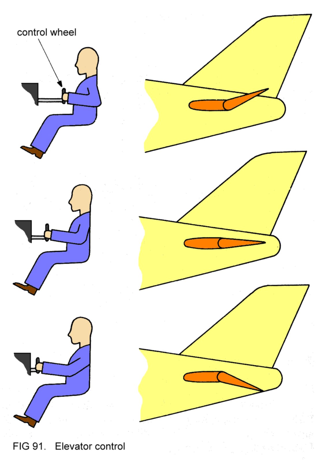
91
Elevator control
92
Rudder control and
nosewheel steering
93
Flap control
94
Elevator trim tab control
95
Magneto switch control
96
Control of electrical
services
97
COM transceiver
98
The headset
99
The transponder
3
DETAILED THEORY OF FLIGHT
100
Airflow past flat plate
inclined at a shallow angle
101
Wing aerofoil shape
102
'Lift' and 'downwash'
103
Wing above stalling angle
104
Relationship between lift
and angle of attack at constant
speed
105
Generation of tail
down-force
106
Disturbance of airflow
107
Effective lift force
108
Induced drag
109
Induced drag generated at
low and high angles of attack
110
Low and high aspect ratios
111
Air spillage at wing tips
112
Angle of incidence and
angle of attack
113
Relationship between
lift/drag ratio and angle of attack
114
Pitching, yawing and
rolling
115
Disturbance causing nose
to
yaw to left
116
Dihedral
117
Sideslip to the left
118
High-winged aircraft in
sideslip to the right
119
Airflow pattern during
sideslip to the left
120
Effect of load disposition
on
CG position of loaded aircraft
121
CG coincident with lift
force
122
CG position behind lift
force
123
Direction of airflow past
propeller blades
124
Propeller blade at most
efficient angle of attack
125
Thrust and torque
126
Difference in rotational
speed at blade roots and tips
127
Airflow direction at roots
and tips
128
Helical twist in propeller
blades
129
Effect of increased engine
power
130
Effect of increased speed
131
Windmilling propeller
132
Forces resulting from
windmilling propeller
133
Propeller efficiency
during take-off
134
Reduced efficiency
resulting from lower blade angle in cruising flight
4
AIRCRAFT HANDLING
135
Picketing
136
Chocks
137
Propeller arc
138
Elevators displaced upwards
139
Effect of elevators
140
Ailerons displaced by
moving the control wheel to the left
141
Ailerons used to select
and maintain an angle of bank of 30° to the left
142
Pilot's view of 30° angle
of bank to the left
143
Yaw caused by bank
144
Pilot's view of yaw caused
by bank
145
Rudder displaced to the
left
146
Effect of rudder
147
Skidding
148
Spiral propwash impinging
on fin-rudder assembly
149
Pitching and yawing in
banked attitudes
150
Unbalanced flight caused
by propwash-induced yaw
151
Unbalanced and balanced
turning flight
152
Airflow past
tailplane-elevator-tab assembly
153
Airflow past
fin-rudder-tab assembly
154
Angle of attack dependent
on relationship between pitch
attitude and actual flight path
155
Disposition of forces in
climbing, level and descending
flight
STRAIGHT AND
LEVEL FLIGHT
156
Generation of required lift
157
Attitudes for level flight
at various speeds
158
Sideslip nullifying action
of fin opposed by application
of rudder
159
Unbalanced straight flight
160
Induced drag during flight
at high and low IAS
161
Variation of drag with IAS
162
Variation of power
required to maintain level flight (at
sea level) with IAS
163
Variation of power
required to maintain level flight (at
various heights) with TAS
CLIMBING
164
Power available and power
required for varying IAS
165
Typical climbing attitude
166
Gradient of climb
167
Climb at maximum rate and
at maximum gradient
DESCENDING
168
Gradient of descent
169
Disposition of forces in
the glide
170
Gradient of descent
dependent upon ratio of required lift to total drag
171
Gliding at low IAS
172
Sideslipping to the left
173
Pitching effects arising
from lowered flaps
174
Forward view enhanced when
flying with flaps down
175
Going around
MEDIUM TURNS
176
Restoring magnitude of
vertical component of lift by increasing lift force
177
Effect of wing tip drag
difference as bank applied
178
Unbalanced flight during
application and removal of bank
179
Typical attitude for
climbing turn with 15° bank
180
Typical attitude for
descending turn with 30° bank
STALLING AND
SPINNING
181
Pre-stall buffeting
182
Operation of stall-warning
vane
183
Causes of downward
pitching at stall
184
Spin to the left
185
Oblique airflow at
pressure head during spin
186
Stall practice at safe
height
187
Entering stall from
straight and level flight
188
Stall occurrence not
directly related to attitude
189
Stalling in abrupt
pitch-up manoeuvre
190
Rudder screened by
elevators when control wheel moved forwards during spin recovery
191
Spin recovery procedure
192
Turning with crossed
controls
THE CIRCUIT
193
Runways
194
Left-hand circuit
195
Positioned for take-off
196
Airborne, accelerating to
climbing speed
197
Take-off profile
198
Effect of wind strength on
climb gradient
199
Crosswind take-off
200
Weathercocking
201
Crosswind blowing aircraft
away from centreline
202
Drifting effect of
crosswind
203
Tracking along extended
centreline in crosswind
204
Wind components
205
Crosswind component
206
Obstacle clearance after
take-off
207
Drift allowance
208
Drift allowance in
crosswind conditions
209
Changing runway appearance
as base leg is flown
210
Final approach
211
Ideal descent gradient
212
Approach too high
213
Approach too low
214
Correction of too-high and
too-low approaches
215
Correction of centreline
displacement
216
The flare
217
Landing attitude
218
Ballooning and its
correction
219
Crosswind from the right
on final approach
220
Crosswind landing
221
Premature elimination of
drift
222
Crossed controls method
for crosswind landing
223
Final stages of short
landing approach
224
Downwind and upwind glide
at minimum gradient IAS
225
Shortening downwind leg
for practice glide approach
226
Reducing and conserving
height surplus on glide approach
base leg
227
Ideal flight path in
practice glide approach
228
Undershooting
229
Extending downwind leg for
practice flapless approach
230
Flapless approach
231
The windsock
STEEP
TURNS
232
Lift increase necessary to
give required vertical
component in banked attitudes
233
Variation of stalling
speed with angle of bank
234
Steep level turns using
45° angle of bank
235
Variation of maximum angle
of bank sustainable in level flight with power
236
45° banked gliding turn to
the left
INSTRUMENT
FLIGHT
237
Instrument scan
VARIABLE-PITCH
PROPELLERS
238
Variable-pitch propeller
239
Engine controls
240
Manifold pressure indicator
5
EMERGENCY HANDLING
241
Courses of action to be
taken following engine failure
242
Choice of field for forced
landing
243
Average field and runway
dimensions
244
Choice of circuit
direction dependent on aircraft height
and orientation relative to field
245
Attempting to prevent
overrunning
246
Forced landing procedure
247
Engine failure at low
height
248
Danger of attempting to
turn back to airfield after
engine failure during climb-out
6
THE FLIGHT MANUAL
249
Taking off with headwind
and tailwind components
250
Wind component
251
Lever arm
252
Moment of empty aircraft
253
Moment of pilot
254
CG positions for empty and
loaded aircraft
255
Permitted range for CG
position
256
Loading table
257
Completed loading table
1 BASIC THEORY OF
FLIGHT
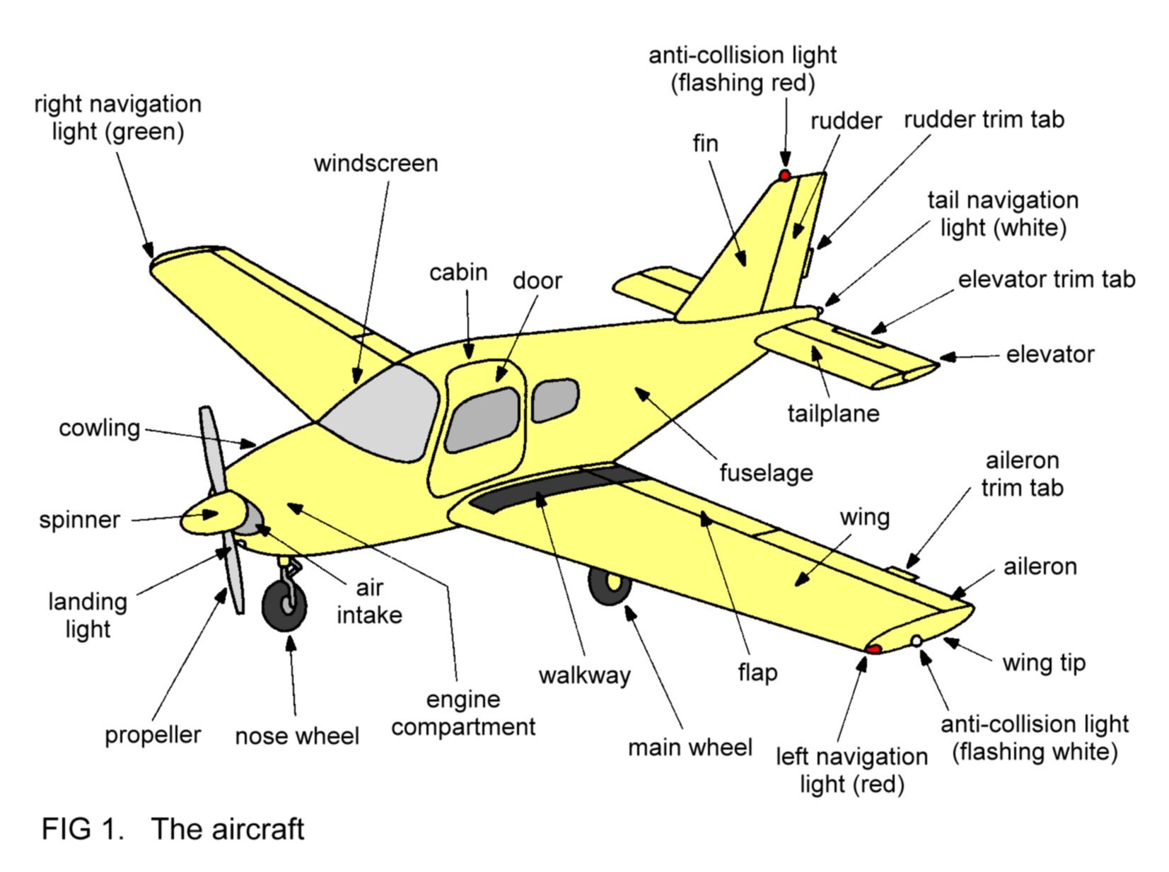
The
design of a typical modern single-engined aircraft is as shown in
Figure 1, with the main features annotated. The front end of the
aircraft is called the nose,
and the rear end is called the tail.
The
design and function of each component will be described later. In this
Section the basic aerodynamic theory of flight will be considered.
(Aerodynamics is the study of the movement of objects relative to the
air.)
All the component parts
of the aircraft have
their own individual weight.
However, it it easier to think of the
separate weight contributions as combining to form a single equivalent
force acting downwards from a point in the aircraft known as the
centre
of gravity,
the single weight force (shown as W in Figure 2)
having the same effect as the combination of the separate forces.

In
order for the aircraft to fly, it is necessary to generate a force
that opposes the weight. This force is generated by the aircraft's
wings when they move through the air and is called lift. Obviously,
each wing contributes half of the total lift generated. However, it is
easier to appreciate aerodynamic relationships if the two separate
contributions are thought of as combining to form a single equivalent
force acting upwards from the centre of the aircraft above the wings,
the single lift force (shown as L in Figure 2) having the same effect
as the combination of
the two separate forces.
Now, in order to
confer aerodynamic stability
to the flight of the aircraft, it is
arranged that the tailplanes each generate a small downward-acting
force. Again, it is easier to think of a single force, called the
tail
down-force,
(TDF), having the same effect as the combination of the
two separate forces. The explanation of aerodynamic stability will
appear later.
In flight at constant
speed and height the disposition of the weight force, the lift force
and the tail down-force is as shown in Figure 2. Notice that the lift
force is slightly greater than the weight force because it also has to
oppose the tail down-force.
Whenever any object
(such as an aircraft) moves through any fluid (such
as air) the fluid tends to
resist the movement of the object. This resistance is called drag and
it can be considered to be a force acting backwards on the object
relative to its direction of movement. As a practical example of drag,
the backward force may be felt if a hand is held out of the window of a
car moving at speed, the force being exerted by the airflow.
All
the components of an aircraft in flight which are exposed to the
airflow generate drag. Again, it is easier to think of the separate
drag contributions as combining to form a single equivalent force
acting backwards from the centre of the aircraft, the single drag
force (D) having the same effect as the combination of the separate
forces.
By careful design, using
the
principle of streamlining,
an aircraft's drag can be minimised.
Streamlining is the designing of components exposed to the airflow so
that they are, as far as
possible, smoothly shaped and elongated. As an example, refer back to
Figure 1 and notice that the engine compartment is carefully shaped so
that it joins the fuselage smoothly and that the fuselage itself tapers
gradually towards the tail, in marked contrast to the design of a
ground vehicle.
The aircraft's drag in
flight is opposed by the
forward-acting thrust
(T) from the propeller,
which is rotated by the
engine. The
importance of streamlining can now be seen - minimised drag
requires only modest thrust to
oppose it. Therefore sufficient power to provide this thrust can be
generated by a small, light, economical engine.
In flight at
constant speed and height, the thrust exactly balances the drag of the
aircraft. In summary, the disposition of forces acting on an aircraft
flying in this manner is as shown in Figure 2.
Note that the thrust
and drag forces are considerably less than the lift and weight forces -
in modern light aircraft the former two are about one tenth the
magnitude of the latter two.
Figure
1 represented a low-winged aircraft. Some light aircraft are
high-winged designs, an example of
which is shown in Figure 3. A feature of many high-winged designs is
the use of struts to improve the load-bearing characteristics of the
wings.

The general aerodynamic
principles outlined in this section apply to
all conventional designs of aircraft.
2 THE AIRCRAFT
Figure 1 showed the layout of a
typical modern
single-engined light aircraft. The aircraft can be considered as
consisting of the engine and the airframe, which is the remainder of
the machine.
2.1 THE
AIRFRAME
In many modern designs
the entire structure of the airframe is of
metal, usually a light, strong aluminium alloy. The following
description refers to such a design.

2.1.1
The wing
The wings are attached
to the fuselage, one on each side. Figure 4 is a
cut-away diagram showing the main features of the left wing.
The lift generated by
the wing in flight is transmitted from the skin
to the ribs,
and thence to the main
spar, which
is bolted to the
fuselage at the wing
root.
The skin is riveted to
the ribs, which are bolted or riveted to the
main spar. In this type of 'stressed skin' construction, the internal
structure has its rigidity and strength enhanced by the attached skin.
In other words, the skin contributes to the supporting of loads
experienced in flight. For this reason, it is important to ensure
before flight that the skin is undamaged, otherwise the structural
integrity of the entire assembly is reduced.
Notice that the ribs
have holes punched into them, to lighten the
weight of the structure. The wing
tip is
usually of metal or
glass-fibre and is attached to the end of the wing to round off its
shape.
A section through A-A
shows the aerofoil
shape of
the wing, as shown
in Figure 5. Notice that the trailing edge is not fixed rigidly to the
main body of the wing, but is mounted on hinged brackets attached to
the auxiliary spar, and is therefore moveable. This moveable part is
called the flap,
and is usually arranged so that it can take up one of
three positions, as shown.

The flap on the left
wing and that on the right wing are linked, so
that both move together. The purpose of the flaps is to alter the
aerodynamic characteristics of the wings to suit the various phases of
flight.
A section through B-B
shows the aerofoil shape nearer the wing tip
(Figure 6).

Again, the trailing edge
is not fixed rigidly to the main body of the
wing, but is mounted on hinges attached to the auxiliary spar. The
moveable part is called the aileron
and is arranged so that it can move
freely up and down within certain limits, as shown.
The aileron on the left
wing is linked to that on the right wing so
that as one aileron moves up the other moves down, and vice versa.
Notice that, to gain
access to the cabin door of a low-winged aircraft,
it is necessary to walk on the top surface of the wing near
the root, which is especially reinforced for this purpose, forming a
walkway. It
is important to realise that other areas of the wing must
never be walked on, since damage will almost certainly be caused to
the skin. This consideration is not, of course, relevant to high-winged
designs.
Sometimes, fuel tanks
are incorporated in the structure of the wing, as
in the example in Figure 4.
The right wing is a
mirror image of the left.
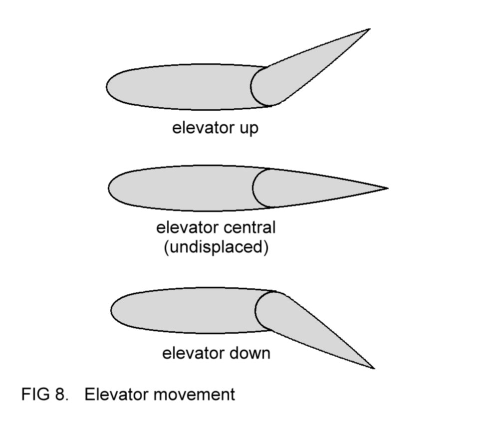
2.1.2
The tailplane and
elevator
The construction of the
tailplane and elevator is similar to that of
the wing. Figure 7 shows the left tailplane and elevator.

The assembly is attached
to the side of the fuselage near the tail. A
section through C-C shows a typical aerofoil shape. The elevator is
mounted on hinges and is therefore moveable up and down within certain
limits, as shown in Figure 8.
Note that the left
elevator is linked to the right, so that they both
move up or down together.
Of course, the right
tailplane and elevator assembly is a mirror image
of the left.
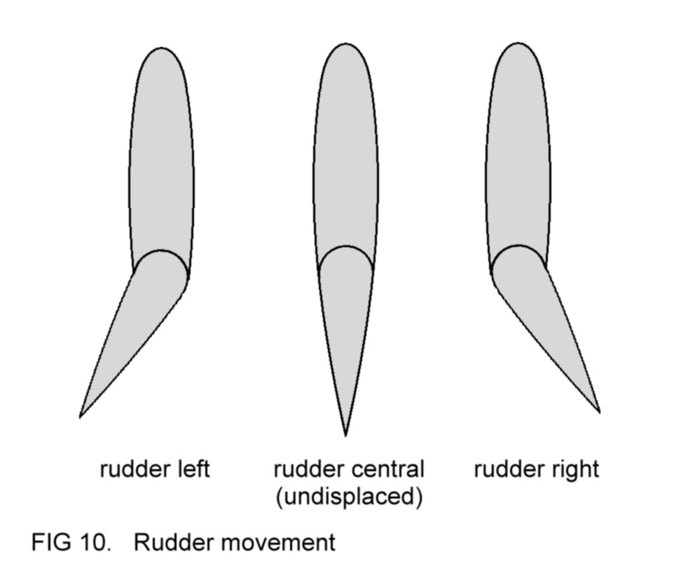
2.1.3
The fin and rudder
The construction of the
fin and rudder is usually of the same pattern
as the tailplane and elevator, as shown in Figure 9.
The assembly is attached
to the top of the fuselage near the tail. A
section through D-D shows a typical aerofoil shape. The rudder is
mounted on hinges and is therefore moveable to the left and right
within certain limits, as shown in Figure 10.
The ailerons, elevators
and rudder are collectively referred to as the
flight
controls,
and they enable the pilot to control the motion of
the aircraft in flight.
2.1.4
The fuselage
Many modern light
aircraft feature stressed skin construction in
their fuselage. A typical arrangement is shown in Figure 11.

The stringers,
which are thin spars running from nose to tail, and the
frames give
the structure its basic rigidity and strength, which again
are enhanced by the skin. The skin is usually attached by rivets.
At the nose end of the
structure is the firewall, made of
metal, to
which is sometimes attached a sheet of fire-proof material. The
firewall
separates the engine compartment from the fuselage and its purpose, as
its name suggests, is to form a barrier ahead of the cabin area so
that, in the event of a fire in the engine compartment, flames are
prevented from entering the cabin. Attached to the firewall are the
engine
mounting points.
These are reinforced areas designed to bear the
weight of the engine assembly, which is bolted to them.
2.1.5
The landing gear
Most modern aircraft
feature a tricycle landing gear, which comprises
three units - two mainwheel
units and a nosewheel
unit. On low-winged aircraft a mainwheel unit is attached to the main
spar underneath
each wing, near the root. On high-winged designs these units are
attached to the lower fuselage beneath the wings. The nosewheel unit
is usually mounted underneath the engine compartment. Each unit
consists of a leg
and a wheel,
as shown in Figure 12.

The purpose of the
landing gear is to support the aircraft whenever it
is on the ground, and also to withstand the loads sustained during
landing. It is noteworthy that most of the aircraft's weight is
supported by the mainwheel units, and their construction is therefore
usually stronger than that of the nosewheel unit.
Figure 12 shows a common
type of landing gear unit - the
oleo-pneumatic type. The leg features a telescopic construction, at the
lower end of which is attached the wheel. Inside the leg are two
compartments, one containing compressed air, and the other oil of a
special kind. It is the compressed air which supports the aircraft on
the ground and absorbs the landing loads. The oil acts as a damping
agent - it
smooths out the telescopic motion of the leg as
the wheel
moves up and down. Thus, between them, the compressed air and the oil
ensure that the aircraft's structure is not jarred during landing or
by manoeuvring on uneven ground.
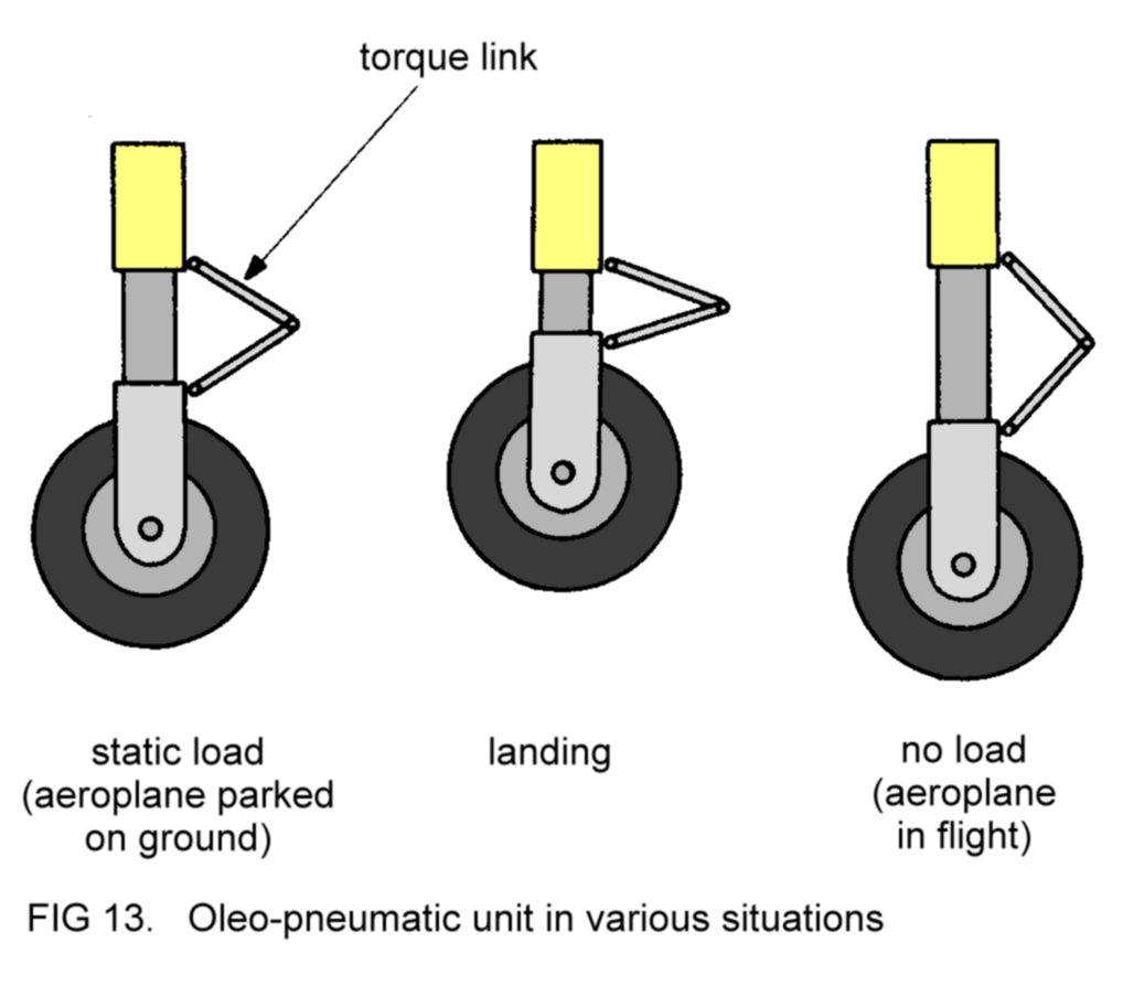
The unit in Figure 12
also features a torque link, the
purpose of which
is to ensure that at all times the wheel is aligned correctly with
respect to the airframe. Figure 13 shows an oleo-pneumatic unit in
various situations.
Each wheel is equipped
with a pneumatic tyre. Once the tyre has been
fitted, it is usual to paint adjacent marks on the tyre sidewall and
the wheel hub, as in Figure 14.
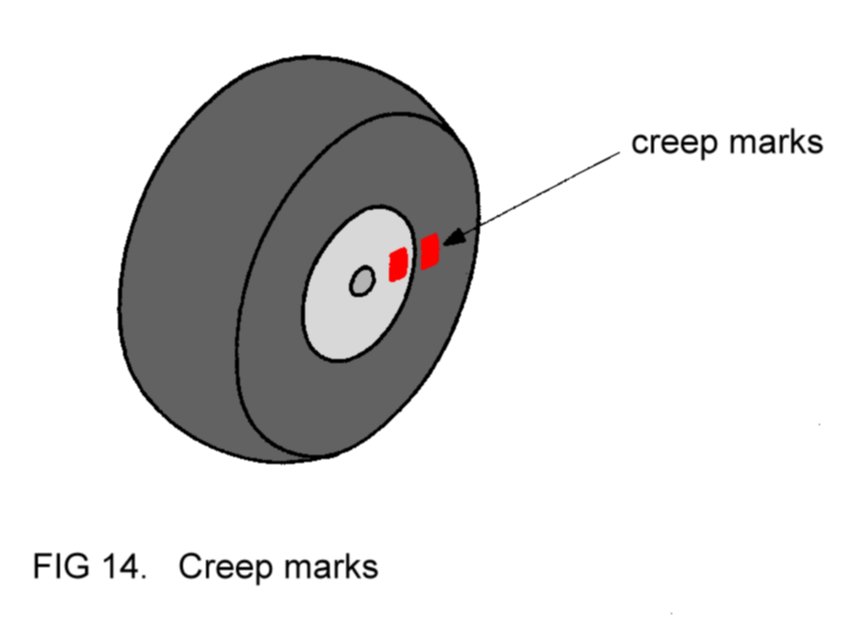
These marks make it easy
to detect any movement, called creep, of the
tyre around the wheel. Such movement is undesirable since damage might
be caused to the tyre valve.
It is normal design
practice to arrange that the nosewheel can be
turned left and right within certain limits, to steer the aircraft
when it is moving on the ground.
Most mainwheel landing
gear units are fitted with brakes, usually of
the disc type, activated hydraulically. Control of the brakes is often
arranged so that the left and right mainwheels may be braked either
together (symmetrical braking) or individually (differential braking).
Symmetrical braking is used to slow down or stop the aircraft when it
is moving on the ground. Differential braking is used to assist with
steering the aircraft on the ground.
On higher performance
aircraft, provision is sometimes made for the
landing gear to be retractable. In other words, the separate units may
be folded up into the airframe, thereby minimising drag during flight.
With low-winged aircraft, the mainwheel units usually retract into
recesses in each wing, whilst on high-winged designs, the recesses are
usually incorporated into the fuselage structure. The nosewheel unit
retracts either into the engine compartment or into the fuselage.
Provision is usually made for folding doors to cover the retracted
units, to smooth out the profile of the airframe and hence further
minimise drag. In many aircraft the retraction mechanism is activated
hydraulically, whilst others may have electrical retraction.
2.1.6
Trim tabs
On many light aircraft,
the trailing edge of one of the elevators
incorporates a trim tab, as shown in Figure 15.

The tab is attached to
the elevator by hinges so that it can move up
and down, within certain limits. A section through E-E is shown in
Figure 15.
Some aircraft also have
trim tabs incorporated in their rudders and
ailerons. Figures 15 represents a trim tab which is adjustable
during flight. Sometimes, fixed tabs are fitted instead, of simpler
construction. They are usually of sheet metal and are attached to the
trailing edge of the appropriate flight control surface. They are
adjustable only when the aircraft is on the ground. Figure 16 shows a
section through a wing which has a fixed trim tab attached to its
aileron. In this example the tab has been adjusted slightly upwards.

The aircraft shown in Figure
1
features
an elevator
trim tab adjustable in flight, and fixed tabs on its rudder and left
aileron. This is a common arrangement.
The function of the trim
tabs is to assist the pilot in the use of the
flight controls.
2.1.7
The cabin
The cabin is
incorporated in the fuselage. It has several features -
the pilot's controls, seats for the pilot and passengers and stowage
for baggage. The cabin is usually enclosed with perspex windows, which
are carefully manufactured to be optically correct so that the
occupants of the cabin may have undistorted vision through them.
In most designs, access
to the cabin is via two doors, one each side,
which are fitted with latches to ensure that the doors remain firmly
closed during flight.
The load intended to be
carried in the cabin (the pilot, passengers and
baggage) is governed by two requirements. Firstly, the aircraft's
loaded weight must not be greater than the 'maximum total weight
authorised' (MTWA) specified in its Flight Manual. Secondly, the
disposition of the load must be such that the position of the centre
of gravity of the loaded aircraft lies within the limits specified.
2.1.8
Other components
Incorporated in the
airframe structure are various components needed to
operate the aircraft. They include:
(a) operating linkages
for activation of the flight controls, flaps and
adjustable trim tabs;
(b) fuel pipelines;
(c) hydraulic fluid
pipelines;
(d) electrical wiring.
Engine control linkages
are routed through apertures in the firewall
into the cabin.
2.2 THE ENGINE
The purpose of the
engine is to drive the
propeller, which in turn provides the thrust necessary for sustained
flight. Nearly all light single-engined aircraft are powered by
internal
combustion
piston engines,
in which fuel (petrol) is mixed
with air and burnt, the heat energy of combustion then being converted
into mechanical energy.
In basic design, these
aero-engines are
similar to those of cars. In certain respects, however, the two types
are quite different. For example, aero-engines are designed to revolve
more slowly, thus reducing the internal stresses, and are of sturdier
construction than car engines designed to give the same power output.
These features minimise the chances of mechanical failure. In this
respect the reliability of modern aero-engines is excellent. Other
differences occur in the design of the ignition systems and the
cooling systems.
In order to appreciate
the workings of an internal
combustion engine, it is first necessary to take note of certain
relevant chemical and physical facts.
2.2.1
Combustion
One
fifth of the earth's atmosphere consists of oxygen gas, most of
the
remainder being nitrogen
gas. In the combustion process, the fuel
combines chemically with the oxygen present in the air. This process
is accompanied by the release of a considerable amount of heat energy.
(The nitrogen in the air plays no active part in the combustion
process.)
2.2.2
Behaviour of
liquids and gases
The working of the
internal combustion engine involves several
behavioural properties of liquids and gases:
(a) when a gas is compressed,
it becomes hotter;
(b) when a fixed volume
of gas is heated,
its pressure increases;
(c)
when a gas flows through a tube which features a constriction, then,
at
the constriction, the speed
of flow of
the gas
increases,
and its
pressure
decreases
(Figure 17). After the gas has passed the constriction, its speed of
flow and
pressure revert to their original values;
(d)
the earth's atmosphere becomes thinner or less dense with
increasing
height. In other words, a given volume at height contains fewer
molecules
of air than the same volume at a lower height;
(e) a gas
at given pressure becomes less
dense as
its temperature increases. In
other words, a given volume at higher temperature contains fewer
molecules
of gas than the same volume at lower temperature;
(f) as a liquid evaporates,
it undergoes cooling
of itself and its
surroundings.

2.2.3
The four-stroke
cycle
The
power that an internal combustion engine delivers is developed in its
cylinders.
Figure 18 shows the component parts associated with one of
the cylinders.
Usually the components
are of steel, except for the cylinder head,
piston and crankcase, which are usually of aluminium alloy.

Consider
now the sequence of events occurring at this cylinder when the engine
is operating. As the engine turns, so the piston moves up and
down in
the cylinder. Notice that the piston is attached to one end of the
connecting
rod,
the other end of which is attached to the crank of the
crankshaft.
It can be seen that, by this arrangement, reciprocating
(up-and-down) motion of the piston is converted into rotational motion
at the crankshaft. The crankshaft drives the propeller.
In Figure
18, the piston is moving downwards.
Notice that the inlet
valve at
the
cylinder head is open,
allowing fuel-air mixture
from the inlet
manifold to
be drawn into the cylinder. The exhaust valve is closed. A
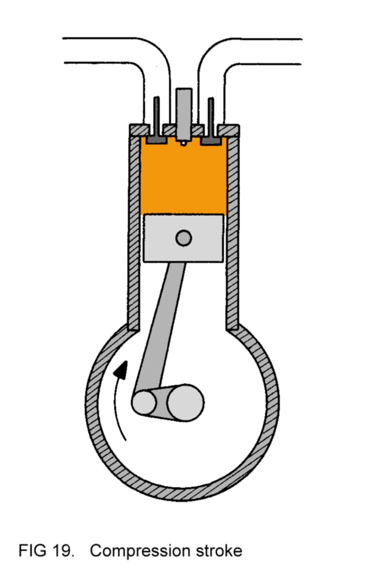
short time later, as shown in Figure 19, the piston is moving upwards.
Since the inlet valve and exhaust valve are now both closed, it will be
appreciated that the fuel-air mixture is being compressed. The
compression has the effect of heating the mixture.
As the piston reaches
its highest position in the
cylinder, the spark plug causes a spark to occur at the cylinder
head. The spark ignites the inflammable mixture, which, because it is
hot and compressed, burns quickly and thoroughly. The heat released
during combustion goes to increase considerably the pressure of the
gases inside the cylinder. In consequence,
the piston is forced down again, giving a rotational impulse to the
crankshaft, as shown in Figure 20.
A short time later, the
piston
starts to move up once more, propelled by the still-rotating
crankshaft, as shown in Figure 21. Notice that the inlet valve is
closed and
the exhaust valve is open,
allowing the piston to drive away
the spent gases into the exhaust
manifold
and thence to the exhaust
pipe, from
which they disperse into the atmosphere.

The cycle of
events then repeats itself. This sequence is called the four-stroke
cycle, and Figures 18, 19, 20 and 21 represent respectively:
(a) the induction
stroke;
(b) the compression
stroke;
(c) the power
stroke;
(d) the exhaust
stroke.
It
should be appreciated that
the piston is delivering power only during
the power stroke.
The impulse given to the crankshaft
during this
stroke is sufficient to ensure that it continues to rotate, propelling
the piston accordingly, during the sequence leading up to the next
power stroke.
In a four-cylinder
engine, the arrangement is such
that, during two complete rotations of the crankshaft, each of the four
pistons delivers one power stroke; in other words, the crankshaft
experiences a power impulse every half-revolution. This feature
enhances the effect mentioned above, ensuring that, at any particular
moment, the continuously-rotating crankshaft is propelling those
pistons which are not involved in delivering a power impulse.
Each
valve is held in the closed position by a valve spring. The valve is
opened, against the pressure of the spring, by an operating mechanism
at appropriate moments during the four-stroke cycle. This operating
mechanism is driven mechanically by the crankshaft, thereby ensuring
that the valve opens and closes at the correct moments in time in
relation to the rotation of the crankshaft.
A typical layout for
a four-cylinder aero-engine is the horizontally-opposed
arrangement,
shown schematically in Figure 22, in which the cylinders are arranged
in two pairs, disposed on opposite sides of the crankcase.

The view
from above shows the offset disposition of the cylinders. This is a
common feature of horizontally-opposed engines and is to allow each
piston to be connected to an individual crank on the crankshaft.
2.2.4
The carburettor
The
carburettor is the means by which liquid fuel and air are mixed in a
satisfactory manner prior to combustion. Figure 23 is a schematic
representation of a float-type
carburettor, used extensively in small
aero-engines.

The carburettor mixes
the fuel and air in the correct
ratio for complete combustion of the fuel. The mixture in the inlet
manifold consists of air, vaporised fuel and tiny fuel droplets. From
the inlet manifold the mixture is drawn into whichever cylinder
is undergoing its induction stroke at that moment. This cylinder will
have its inlet valve open - all the others will have theirs closed.
As
the mixture is taken from the inlet manifold, so air is drawn into the
intake tube of the carburettor to replace it. In many designs the
incoming air passes through a filter whose function is to remove any
foreign matter such as dust or grit which might otherwise damage the
engine if ingested. Notice that the intake tube features a streamlined
constriction,
sometimes called the choke. The air
flowing past it
undergoes a reduction
in pressure
(as was shown in Figure
17) which has
the effect of drawing fuel from the fuel nozzle, located in the intake
tube at the constriction. As it is drawn from the nozzle by the air
speeding past, the fuel is broken up by the air into droplets. In other
words, it is atomised.
The smaller droplets evaporate in the air - the
larger ones are carried along with it. It can be seen that, by this
process, new mixture has been created to replace that taken into the
cylinders.
As fuel is drawn from
the nozzle, the level of fuel in
the float chamber
drops and so the float is no longer forcefully held
up. Reference to Figure 23 shows that when this happens, the float
valve on
the other side of the pivot will rise under the
pressure of
the fuel from the pump. Accordingly, more fuel will enter the float
chamber until the level has risen sufficiently, urging the float to
rise with it, for the float valve to be lowered again,
thereby cutting
off the flow of fuel.
The cycle then repeats
itself. In this way,
the float chamber is constantly replenished with fuel to replace that
drawn from the nozzle. In practice, when the engine is running, a
steady state of affairs is reached, as in Figure 23, with the float
slightly lowered from its highest position and the float valve slightly
raised, permitting fuel to flow into the float chamber at the same
rate as it is drawn from the nozzle.
2.2.5
The throttle
The throttle is the
means by which the power output from the engine is
controlled.
The
amount of mixture passing from the carburettor into the inlet manifold
is controlled by the throttle
valve. The
valve, shown in Figure
23, is
in the form of a circular plate located in the intake tube just above
the fuel nozzle. The plate can pivot about its centre, thereby
effectively varying the area of the intake tube through which the
mixture passes and hence controlling the amount of mixture supplied to
the inlet manifold.
The position of the
throttle valve is controlled
by the throttle
lever,
to which it is linked. When the lever is used to
make the valve pivot so as to cut off almost completely the mixture
supply to the cylinders, as shown in Figure 24, the throttle is said
to be closed.

In this situation, after
combustion, the increase of
pressure of the gases in the cylinders is not very great, and so the
pistons deliver only weak power impulses. In other
words, the power
output from the engine is minimal.
As the lever is used to open
the throttle progressively, it causes the
valve to pivot so
as to allow more mixture to enter the cylinders for combustion, and the
pistons therefore deliver stronger power impulses - the power
from the
engine increases.
Figure
23
shows an intermediate throttle
setting.
When the throttle is
fully open, therefore, the engine delivers its
maximum power, with the valve as shown in Figure 24.
2.2.6 Mixture
strength
and mixture control
It
has been stated that the carburettor mixes the fuel and air in the
correct ratio for combustion. Obviously, it must fulfil this function
regardless of the setting of the throttle valve. When the valve is
set to give low power output it partially restricts the air flowing
through the intake tube, as described above. Because the flow of air is
restricted, the pressure reduction at the constriction is less marked,
and so less fuel is drawn from the nozzle. Conversely, the throttle
valve set to give high power output allows a strong flow of air through
the intake tube, with the result that the pressure reduction at the
constriction is more marked and so more fuel is drawn from the nozzle.
Thus it can be seen that the very design of this type of carburettor
automatically matches the fuel supply to the amount of air entering the
intake tube.
Under certain
circumstances, however, the fuel supply
must be modified for reasons which are explained below, and,
accordingly, the carburettor is designed to be able to bias the mixture
either with extra
fuel (giving a rich
mixture strength) or with fuel (giving a lesslean
mixture strength). Very lean mixtures are referred to as being weak.
When the engine is
operating at high power output,
for example during take-off, the carburettor is made to supply a rich
mixture. The extra fuel, when it vaporises, helps to cool the
mixture. This ensures that, after being heated during
the compression stroke, the mixture is not above the right
temperature for correct combustion. In addition, the cylinders and
pistons are prevented from becoming overheated. Note that the purpose
of the extra fuel is solely to cool the mixture by evaporation - it
does not increase the engine power output, since all that happens
during the combustion process is that the available oxygen in the air
is shared by however much fuel there happens to be in the mixture.
With
increasing height, the earth's atmosphere becomes less
dense. If an aircraft is cruising at height, therefore,
the carburettor will be taking in this less dense air. However, the air
pressure reduction at the streamlined constriction is still
considerable - enough to draw out fuel from the nozzle at a rate which,
because of the reduced density of air, would yield a mixture over-rich
in fuel. This over-rich mixture would cause poor fuel economy - that
is, less distance flown through the air for each litre of fuel used -
and possible rough-running of the engine.
To prevent this, the
carburettor is fitted with a mixture
control,
represented schematically
in Figure
23. The
control
takes the form of a variable restriction in
the fuel supply from the float chamber to the nozzle. To correct
over-richness at greater heights the control is operated to restrict
the flow of fuel to the nozzle, thus bringing the mixture to the
correct strength for the prevailing density of air. Appropriate use of
the mixture control will therefore improve the fuel economy and ensure
smooth running of the engine.
The mixture control is
progressive in
its operation - when positioned so that the fuel supply is unrestricted
(the 'rich' position), as in Figure 23,
the carburettor would give the
rich mixture necessary for high engine power output, if needed, whilst
for cruising flight, the control would be used as necessary to give the
correct mixture strength at the chosen height - the greater the height,
the more the control should be moved away from the 'rich' position to
restrict the fuel supply further. This process of correcting the
mixture strength for height is called 'leaning out' the
mixture. Figure
25 shows the mixture control set to an intermediate position.

The position of the
mixture control is set by a lever to which it is
linked.
Note
that, for any particular throttle setting, regardless of whether the
mixture is correctly leaned out or not, an engine equipped with the
type of carburettor described here delivers less power at greater
heights than it does at lower heights. This is because a cylinder-full
of mixture at greater height contains fewer molecules of oxygen
available to combine with the fuel.
Usually, on small
aero-engines,
the mixture control is not automatic in operation - it is set as
necessary by the pilot and is adjustable in flight. Because of this,
care must be taken to ensure that the control is not used to make the
mixture too weak when a richer mixture is required, for example at high
engine power output or when cruising at low height.
If the
throttle is opened very quickly, the throttle valve permits a sudden
increase in the flow of air entering the intake tube. However, because
of its inertia, the supply of fuel from the float chamber to the
nozzle cannot immediately match the demand, with the result that
temporarily fuel starvation occurs, and an over-weak mixture is
supplied to the inlet manifold. This effect is only momentary because
soon the fuel flow overcomes its inertia and is able to supply the high
demand at the nozzle. However, with some carburettor designs, the
weakness of mixture may be sufficiently marked to cause the engine to
cease to deliver power temporarily, a dangerous consequence which is
obviated by incorporation in the carburettor of an accelerator
pump.
This device is activated mechanically when the throttle is opened, and
causes an extra squirt of fuel to be supplied to the intake tube for a
sufficient length of time to prevent the weakening of the mixture that
would otherwise occur. Figure 23
includes a schematic representation of
the accelerator pump.
2.2.7
Carburettor heat
control
At
the fuel nozzle, the evaporation of fuel droplets has the effect of
cooling the intake tube to the extent that, if
the air is sufficiently humid, ice may form in the intake tube. This
phenomenon is called 'carburettor icing' and can occur even in warm
ambient temperatures if the air is sufficiently moist. If the build-up
of ice is heavy, it can block the intake tube so much that the supply
of air passing through it is impeded, causing the engine to lose power
and run roughly. In severe cases, total loss of power is possible.
To
guard against this occurrence, a carburettor
heat control
is fitted.
When selected 'on',
the control shuts off the normal supply of air to
the intake tube whilst at the same time opening an alternative supply.
The air from this alternative supply is pre-heated, usually by passing
through a muff fitted round the engine's exhaust pipe. When it enters
the carburettor, this pre-heated air melts any ice which may be
present. The resulting water then passes through the engine to be
ejected with the exhaust gases. Figure 26 shows the control selected
'on'.

When the control is 'off',
the pre-heated air supply
is shut off and the normal supply of unheated air comes back into use,
as in Figure 23.
Note that whenever the
heat control is 'on',
the engine delivers slightly less power for a particular throttle
setting than when the control is 'off'. This is because the pre-heated
air is less dense
than the unheated air and so
a cylinder-full of mixture contains fewer molecules of oxygen available
to combine with the fuel. For this reason, the engine is normally
operated with the control 'off'.
The control is selected
'on':
(a) for periods of a few
seconds every few minutes or so, to ensure
that any ice in the carburettor is dispersed;
(b)
if the engine develops rough-running or loss of power and it is
suspected that carburettor icing may be causing the malfunction. In
this case, the control is left 'on' until all the ice has been
dispersed;
(c) on some designs of
engine whenever low power settings
are in use for protracted periods of time. These engines are
susceptible to icing around the throttle valve when it is set for low
engine power.
Note that, if the
control is used as described in (a),
then it is unlikely that carburettor icing would build up to the extent
that loss of power or rough-running of the engine occurred - prevention
is better than cure.
The position of the
control is set by a lever to which it is linked.
2.2.8
Detonation
During
the power stroke of the four-stroke cycle, the mixture burns steadily
and evenly and the increase of gas pressure on the piston is therefore
smoothly progressive. However, if the engine controls are not being
used correctly, it is possible to arrive at a situation where the
temperature of the mixture just prior to ignition is too high for
normal combustion. Instead of smooth, progressive combustion, the
over-heated mixture in the cylinder burns explosively, resulting in a
sudden harsh increase in pressure that can strain the piston and
possibly even damage it.
This explosive
combustion is called 'detonation' and can occur for one
of three reasons:
(a)
incorrect mixture strength. If the throttle is set to give high engine
power output, then the mixture must be rich, as already
mentioned in
2.2.6, to help to keep it cool. If the mixture is too weak, its
temperature may increase during the compression stroke to the extent
that, after ignition, detonation occurs;
(b) incorrect use of
carburettor heat control. With the control 'on', the mixture supplied
to the cylinders has a higher temperature than with the control 'off'.
At high engine power output, this increase in temperature, which is
raised further during the compression stroke, may be sufficient to
cause detonation;
(c) incorrect grade of
fuel.
Notice that
detonation is most likely to occur at high engine power output, and can
be avoided in these circumstances by ensuring that the mixture
control
is set to 'rich'
and that the carburettor
heat control is
'off'.
2.2.9
Fuel injection
Some
aero-engines, usually those of higher power output, feature a fuel
injection
system instead of a float-type carburettor.
These injection
systems are considerably more complicated and therefore more
expensive, but they do confer several advantages, not the least of
which is the elimination of the possibility of carburettor icing.
A
detailed description is outside the scope of this book. The basic
operating principle is that fuel is injected into the air entering each
cylinder during its induction stroke. Otherwise the operation of the
engine is similar to that already described.
2.2.10 The
ignition system: the magneto
The
ignition system is designed to supply electric current to the spark
plugs in the cylinder head. The current is generated mechanically by
the magneto,
which is a modified form of electric dynamo.
2.2.10.1
Mechanical
generation of electricity
Mechanical
generation of electricity makes use of the interaction of a rotating
magnet with a coil of metal wire. A schematic arrangement is shown in
Figure 27. Alternatively, the coil can be designed to rotate inside a
magnet array.

In either case, electric
current is generated in the
coil as long as rotation occurs. When rotation stops, no current is
generated.
2.2.10.2
Conversion to
high voltage
The device in
Figure 27 can be considered as an 'electricity pump', and accordingly,
the electricity delivered from it has a 'pressure' (in the same way as
a water pump delivers water under pressure). This pressure is
termed voltage.
Not surprisingly, the voltage depends on the speed of
rotation of the magnet - faster rotation gives greater voltage.
In
an aero-engine magneto, the spindle to which the magnet is attached is
rotated by the engine's crankshaft via a suitable arrangement of gear
wheels.
The voltage produced by
the coil when the engine is running
normally is very considerably less than that required by the spark
plugs, and so the electric current has to be modified. The
modification is achieved by two devices - the contact-breaker and
the
transformer.
The contact-breaker interrupts the electric current from
the coil at suitable intervals. Each interruption causes an electrical
interaction in the transformer (which is merely a particular
arrangement of coils of metal wire), producing a pulse of high voltage
electric current from it.
2.2.10.3
Timing and
distribution
The
high voltage pulses are supplied to the spark plugs in the cylinder
heads. Obviously, the pulses must be made to occur at precise moments,
so that, in each cylinder, the spark occurs as the piston reaches its
highest point in the cylinder at the end of the compression stroke.
The
correct timing
is ensured by the contact-breaker, which is operated
mechanically by the spindle, causing interruptions in synchronisation
with the spindle's rotation. By this means, the pulses from the
transformer are automatically made to occur at precisely the correct
moments during the rotation of the crankshaft, regardless of the speed
of rotation.
All that remains is to
ensure that the pulses are
delivered to the individual spark plugs in the correct sequence.
This is done by the distributor.
The distributor has a rotating arm,
driven round by the spindle, which directs the pulses from the
transformer to the spark plugs via their respective ignition
leads,
which are suitable lengths of heavily insulated electrical cable.
The
term 'magneto' applies to the entire assembly of components described
above. The components are arranged such that the spindle can drive all
the rotating parts. When the magneto is bolted to the engine's
crankcase, its spindle connects with gear wheels driven by the
crankshaft.
A schematic
representation of the electrical set-up is shown in Figure
28.

2.2.10.4
The spark plug
Figure 29 shows a
section through a spark plug screwed into its
cylinder head.

When
the high voltage pulse is sent to the spark plug from the
distributor it travels down the centre
electrode
and then, in the form
of a spark, it jumps across the small gap to the 'earth' electrodes.
(All the electrodes are of metal.) From the earth electrodes the
electric current flows to the outside case of the plug and then away
via the cylinder head into the main body of the engine, where it
dissipates. The ceramic insulation prevents the pulse from leaking
across to the plug case before it reaches the end of the centre
electrode.
The electric pulses
travelling from the distributor to the spark
plugs would cause
interference on the aircraft's radio equipment, and to prevent this,
the ignition leads are 'screened' - in other words, they have an outer
sheathing of finely-woven metal wire.
2.2.10.5
Dual ignition
systems
Most
aero-engines are equipped with two magnetos. In these dual ignition
systems, each cylinder has two spark plugs, one supplied by each
magneto, figure 30 shows a schematic arrangement for a four-cylinder
engine.

There are two advantages
of dual ignition systems:
(a) in
the event of failure of one of the magnetos, the other will still
supply one spark plug in each cylinder with high voltage pulses;
(b)
with both magnetos operating, the mixture in the cylinders is ignited
at two different locations, which makes for more efficient combustion,
and therefore better power output from the engine.
Note that these
aero-engine ignition systems are entirely self-contained and need no
external supply of electricity. (In this respect they differ from car
engine ignition systems, which require the battery to supply the
electrical current to the transformer.)
2.2.10.6
The impulse
magneto
When
the engine is being started from rest, the crankshaft, and therefore
the rotating components of the magnetos, are turning much more slowly
than when the engine is running normally. Because of this, the high
voltage pulses are much weaker than normal - so weak that they may not
be able to jump from the centre electrodes of the spark plugs to the
earth electrodes. If this is the case then no sparks occur and so no
ignition takes place.
To overcome this
problem, it is arranged that
one of the magnetos of the dual ignition system, termed the impulse
magneto,
has its spindle rotated, not steadily, but in
impulses. This
impulse drive is achieved mechanically by an arrangement of springs and
weights within the magneto, and occurs whenever the spindle is rotating
very slowly, as during start-up. During each impulse, the spindle
momentarily rotates faster - enough to ensure that sparks occur at the
cylinder heads.
Once the engine is
running normally, the magneto automatically reverts
to direct drive
2.2.10.7
Ignition control
Each
magneto is controlled remotely by its own magneto
switch.
When the
switch is on,
the contact-breaker causes interruptions in the electric
current from the coil and the magneto functions normally.
When
selected off,
the switch allows the electric current from the coil to
bypass the contact-breaker. Accordingly, no interruptions occur and no
high voltage pulses are delivered to the spark plugs. If both
magnetos are switched off, combustion of the mixture cannot be
initiated and so the engine no longer delivers power.
Figure 31 shows a
magneto switch diagrammatically.

2.2.10.8
Electronic
ignition systems
A recent development in
aero-engine technology is the replacement of
conventional magnetos by electronic
ignition systems.
These have several advantages, including
fewer mechanical components (thereby reducing maintenance requirements)
and more precise timing of the high voltage pulses delivered to the
spark plugs, which promotes more
efficient fuel combustion and thereby enhances engine power output and
fuel economy.
2.2.11 The
oil system
It
is apparent that the internal combustion engine has many moving parts.
When the engine is operating, there would be friction between these
parts as they moved against each other, causing excessive wear and
overheating, were it not for the presence of a lubricant. The lubricant
used is oil,
an adequate supply of which is delivered to all moving
parts in the engine.
Wherever the machinery
has to withstand high
stresses, as in the crankshaft bearings and connecting rod bearings,
the oil is delivered under
pressure.
(The crankshaft bearings are the
housings in the crankcase which support the crankshaft. The connecting
rod bearings are the housings at the end of the connecting rods in
which the cranks rotate.) The pressure feed ensures that a film of oil
is forced in between adjacent metal surfaces to prevent their contact.
Other
moving parts where the stresses are not so great are lubricated either
with oil under pressure or by oil
spray. On
spray-lubricated parts, an
adequate oil film forms without the need of pressure. The layout of a
typical oil system is shown in Figure 32.

The
sump, in
which the oil is stored, is a deep metal tray forming the
lower part of the crankcase. From the sump the oil, still hot from its
circulation through the engine, is drawn by the pump through the
suction
screen,
which filters foreign matter from the oil. From the
pump the oil is piped, now under pressure, to the oil cooler. In the
cooler the oil passes through a matrix of thin tubes which are exposed
to the airflow experienced by the aircraft in flight, enabling the oil
to lose much of its heat to the airflow.
The oil is now delivered
to
the pressure screen, where it is again filtered. On the way, automatic
measurements of the temperature and pressure of the oil are made and
transmitted to calibrated gauges in the cabin.
From the pressure
screen the oil is directed through drillings in the crankcase to the
crankshaft bearings and, through holes drilled in the bearings, into
the hollow crankshaft, from which it is fed to the connecting rod
bearings, again via holes drilled in the bearings. From these bearings
the oil forces its way out in the form of a spray.
The resulting oil
spray lubricates the cylinder walls and the piston bearings housing the
other ends of the connecting rods. Part of the spray is collected in
oil channels through which it flows to lubricate other moving parts in
the engine.
The inlet and exhaust
valve operating mechanism is usually lubricated
by oil under pressure, taken from the pressure supply.
Having fulfilled its
lubricating function, the oil drains back into the
sump.
Note
that, in order to ensure an adequate supply at all times when the
engine is operating, the oil pump is designed to deliver more than is
needed. The pump is driven by the crankshaft via a series of gear
wheels. Hence faster rotation of the crankshaft causes the pressure of
oil delivered from the pump to rise. When the maximum designed pressure
is exceeded, the surplus oil is diverted by the pressure
relief valve
back into the sump.
When the oil is very
cold, for example before
the engine is started in wintry weather, it is so thick that it does
not flow easily through the fine tubes of the cooler. Obviously, in
this case, the cooler is acting as an obstruction to the flow of oil,
and there is a danger that its tubes might be damaged by the oil under
pressure. However, the pressure build-up caused by the obstruction is
sensed by the by-pass
valve,
which opens to allow the oil to by-pass
the cooler. Once the engine has warmed up, the now thinner oil can flow
more easily through the cooler and the by-pass valve closes to make
sure that it does so.
The oil system of some
designs of engine may
differ in certain respects from the arrangement described here, but the
basic operating principle is the same in all designs.
The oil system
also serves a secondary purpose - that of cooling the inner parts of
the engine, which give up their heat to the oil as it flows through. In
turn, the oil loses the heat as it passes through the cooler.
2.2.11.1
Oil quantity and
consumption
Not
all of the oil returns to the sump after it has been pumped round the
engine - some escapes past the pistons and is burnt along with the
fuel-air mixture. This loss is referred to as the engine's oil
consumption.
If the level of oil in the sump drops below a
certain
level as a result of the loss, then the pump may not be able to deliver
an adequate supply to the engine. The consequent oil starvation would
cause, initially, overheating of the engine because of the increased
friction, and eventually, mechanical failure of the engine.
Because
of these dangers, the manufacturer will specify the minimum
permitted
quantity of
oil required in the sump and also the maximum
permitted
rate of consumption
(in terms of amount consumed per hour
of engine
operation).
Before every flight,
therefore, the pilot is responsible
for ensuring that the quantity of oil in the sump is at least equal to
the minimum permitted quantity plus
the amount that would be consumed
during the flight. An engine
which is found to lose oil more quickly than the maximum permitted
rate must be withdrawn from service until the fault is remedied.
In
most designs, the quantity of oil in the sump is measured with a
calibrated dip-stick, which is often integral with the filler cap. If
the dip-stick indicates a quantity less than that needed for the
flight, extra oil is added through the filler opening.
2.2.11.2
Oil grade
The
oil used for engine lubrication is refined to a very high quality. It
is also graded according to its thickness, or viscosity. Oil of
high
viscosity is thick and treacly; that of low viscosity is thin and runny.
Oil
suffers from the drawback that its viscosity reduces as its temperature
increases. At very high temperatures, the oil may become so thin that
the lubricating films in the engine may break down, with consequent
detriment to the machinery. Conversely, at very low temperatures, the
oil becomes very thick, so much so that it may be difficult to turn the
engine for starting. Additionally, once the engine is running, the oil
pipes may be subjected to excessive strain.
To overcome these
problems, oil grades are chosen to suit the ambient conditions. For
example, during summer-time operations, oil of higher viscosity is used
to that as the engine reaches its normal operating temperature, the oil
is still thick enough to be able to perform its lubricating functions
adequately.
In winter, use of a
lower viscosity oil will ensure that
engine starting is not hampered and that the oil system is not
overstrained when the oil is cold. On some engine designs, it can be
arranged that during cold weather, the flow of air through the oil
cooler is restricted to assist the oil to warm up to a satisfactory
working temperature.
The engine manufacturer
will specify the grades
of oil to be used according to ambient temperature, and most engines
have this information placarded adjacent to the oil filler cap for ease
of reference. From what has been stated above, it is apparent that use
of an incorrect grade is potentially harmful to the engine.
2.2.11.3
Dry-sump systems
The
oil system represented by Figure 32 is termed a wet-sump
system,
because its oil is stored in the engine sump. This layout is found in
many training and touring light aircraft. However, some machines are
designed to be aerobatic - that is, capable of performing extreme
manoeuvres such as loops and rolls.
Obviously, for these
aerobatic
types, the wet-sump oil system would not be satisfactory, because the
oil would be thrown around during manoeuvres, with a danger that the
supply to the oil pump might be interrupted. This drawback is overcome
by storing the oil in a separate tank designed to ensure an adequate
supply to the pump regardless of the motion of the aircraft. After
being pumped round the engine the oil drains to the sump and is
removed by a scavenge
pump which
returns it to the tank. This
arrangement is called a dry-sump
system.
2.2.12
Engine cooling
Ideally,
all the heat energy generated in the cylinders during combustion of the
fuel would be converted by the engine into mechanical energy, but this
is not achievable in practice. Much of the heat energy is wasted - some
is taken away by the exhaust gases and some goes to raise the
temperature of the cylinders and their associated components. If
nothing were done about it, these parts would rapidly heat up to the
extent that the lubricating oil films would break down. When this
happens, of course, the eventual consequence is mechanical failure of
the engine.
Obviously then the heat
must be taken away before it can do any damage
- the engine must be cooled.
Most aero-engines are air-cooled.
The cylinders and cylinder heads are
made with integral metal fins
surrounding their outsides, as shown in
Figure 33.

When the aircraft is in
flight, part of the airflow
that it experiences is made to flow through the fins, which give up the
heat they have taken from the cylinders to the passing air. By this
means the working temperature of the engine is kept at a reasonable
level.
In a multi-cylinder
engine the cooling airflow is directed by baffles
such that each cylinder receives an adequate supply.
When
the aircraft is on the ground with its engine running, it is apparent
that there will be no strong airflow past the fins, and so it is not
easy for the engine to get rid of its excess heat. To a certain extent
the situation is alleviated by the effect of the air thrown back by the
rotating propeller. Some of this air flows through the fins, helping to
take away the heat. Nevertheless, it is essential that to prevent
overheating in these circumstances the pilot exercises care in the use
of his engine controls, avoiding high power settings whenever possible.
2.2.13
The propeller
The
propeller is an assembly of specially-shaped blades which is rotated by
the engine to provide thrust. In section, the blades have a similar
aerofoil shape to the wings, and they generate thrust in the same
manner as the wings do lift.
The most common design
for light aircraft is the two-bladed fixed-pitch
propeller, usually made of
aluminium alloy. A fixed-pitch propeller is one in which the blades are
attached to the hub at a fixed angle.
The propeller is bolted
to the
end of the crankshaft. To streamline the hub, and thus minimise drag in
flight, the propeller is usually fitted with a spinner, which is a
shaped metal cone bolted to the hub. Figure 34 shows a typical
propeller design.

2.2.14
Engine mounting
The
entire engine assembly with all its components and accessories (which
will be described later) is housed in a rigid framework of strong steel
tubing. This in turn is bolted to the engine mounting points on the
firewall at the nose end of the fuselage structure.
2.2.15
The cowling
Figure
1 shows that
the engine compartment is enclosed by a
cowling,
the main purpose of which is to streamline the shape of the
nose end of the aircraft to minimise drag in flight. The cowling
usually incorporates intakes from which air is ducted for engine
cooling purposes. This air, having taken heat from the fins of the
cylinders, flows out again from vents in the rear of the cowling. With
some designs, the vents are partly covered by cowl flaps, which
are
opened to maximise the cooling airflow whenever engine overheating is
most likely to occur, as during ground running and while flying at low
speed with the engine at high power. In cruising flight, with power
reduced and the aircraft at higher speed, the cowl flaps can be closed
to restrict the airflow and so prevent the engine from being cooled
below its designed operating temperature.
Other intakes in the
cowling supply the oil cooler and the carburettor
with air.
In
modern machines the cowling is either of aluminium alloy or of
glass-fibre and features hinged portions which can be opened for engine
inspection before flight.
2.2.16
The tachometer
The
tachometer enables the pilot to assess the power output from the
engine. It is mounted on a panel in front of the pilot called the
instrument
panel,
and indicates the speed of rotation of the crankshaft
in terms of revolutions per minute (RPM). Of course, the propeller RPM
are exactly the same, since the propeller is bolted to the crankshaft.
The tachometer is driven
either mechanically or electrically. Its
presentation on the instrument panel is as shown in Figure 35.

The
tachometer gives a direct indication of engine power output, higher RPM
signifying higher power output. To appreciate why this is so, remember
that when the throttle is opened, it causes the pistons to deliver
stronger power impulses to the crankshaft, forcing it to rotate more
quickly.
The red-line marked on
most tachometers indicates the
maximum permitted engine RPM. In the example shown the red-line is at
2700 RPM.
2.2.17
Engine-driven
systems
Besides its chief task
of rotating the propeller, the crankshaft must
also drive other components. Some of these are integral with
the engine
and have already been mentioned, namely:
(a) the inlet and
exhaust valve operating mechanism;
(b) the oil pump and
fuel pump;
(c) the magnetos.
Additionally, external
accessories are powered by the crankshaft. They
are:
(a) the alternator in
the electrical system;
(b) the suction pump
which activates the gyroscopic flight instruments;
(c) the hydraulic system
pump.
Most
light aircraft are equipped with electrical and suction systems.
Engine-driven hydraulic systems are most likely to be found on machines
incorporating retractable landing gear.
It is usual for the
suction
pump and hydraulic pump (where fitted) to be driven directly via a
series of gear wheels. In contrast, the alternator is usually driven by
a belt of reinforced rubber which passes round two pulley wheels, one
on the alternator, the other on the crankshaft (as in car engines).
2.2.18 FADEC
systems
We have seen that some
aero-engines feature fuel injection systems for
delivering fuel to the cylinders rather than carburettors and noted
that a benefit of these systems is the elimination of the possibility
of carburettor icing. We have also seen that electronic ignition
systems offer several advantages over conventional mechanical magnetos.
A further development which enhances engine efficiency is the Full
Authority Digital Electronic Control (FADEC) system fitted to some new
engines.
In a FADEC engine,
sensors measure various parameters and send this
data to a computer, which controls both the flow of fuel fed to the
cylinders and the precise moment in the four-stroke cycle that the
spark is triggered in the spark plugs, further improving engine
efficiency and power output.
The parameters sensed
include:
(a)
the throttle lever position;
(b) actual engine RPM;
(c) ambient air pressure
and temperature;
(d) air pressure in the
inlet manifold;
(e) the temperature of
the cylinder heads;
(f) the temperature of
the exhaust gases.
In aircraft fitted with
FADEC engines, then, there is no need for
a mixture control lever or a carburettor heat control lever.
Usual
practice is for two independent
computers to be incorporated in the system so that normal engine
operation is retained even after failure of one of the computers.
2.3 THE FUEL
SYSTEM
The
fuel used by the aircraft's engine is stored in tanks, from which it
is fed to the carburettor by the fuel pump. Figure 36 shows a typical
arrangement for a fuel system having one tank in each wing. In other
designs, tanks may be located in the fuselage.

Every tank has a vent
to allow air to replace the fuel taken from it. In this way there is no
danger of suction building up in the tank, which might prevent more
fuel from being drawn from the tank by the fuel pump.
The fuel cock
selects the tank(s) from which the fuel is taken at any particular
time. With some designs it is only possible to feed from one tank at a
time. Others allow fuel to be drawn simultaneously from more than one
tank. The fuel cock also enables the fuel supply to the engine to be
completely cut off when required.
From the fuel cock the
pipeline leads to the engine-driven fuel pump, which pumps fuel to the
carburettor whenever the engine is running. On the way, automatic
measurement of pressure is made and transmitted to a gauge in the cabin.
To
guard against the possibility of fuel starvation caused by failure of
the engine-driven pump, many systems incorporate an electrically-driven
pump as a back-up. This is switched on as necessary in accordance with
the manufacturer's recommendations.
It is usual to include fuel
drains
in the system at appropriate points. Before flight, or as recommended,
the drains are opened briefly to allow any water or sediment which may
have accumulated to be expelled. As an extra safeguard, the fuel is
filtered by a strainer
before it reaches the pumps.
On some engine designs,
a hand-operated primer
is used for engine starting. When operated, the primer injects neat
fuel into the inlet manifold adjacent to each cylinder inlet to ensure
an adequate supply during the starting procedure.
2.3.1
Fuel quantity and
consumption
The
quantity of fuel in each tank is automatically measured by electrical
apparatus and the measurements are transmitted to calibrated gauges in
the cabin. However, the pilot should visually check the quantity in
each tank before flight to satisfy himself that the gauges are
indicating reliably. (This procedure is not possible with some designs
of aircraft.)
The
tanks are replenished as necessary through the filler openings. During
this operation, precautions must be taken to minimise the attendant
fire hazard. These include the prohibition of smoking and naked flames
in the vicinity of the aircraft.
The rate at which the
engine consumes fuel depends on two factors:
(a) the throttle setting;
(b) the mixture control
setting.
Consumption
is highest when the throttle is fully open and the mixture control is
set to rich. The aircraft's Flight Manual will detail the rates of
consumption for various settings of the engine controls. It is the
responsibility of the pilot to ensure that the tanks contain sufficient
fuel (including reserves) for the intended flight.
A point to bear in mind
is that,
during flight, the total quantity of fuel remaining in the tanks is
always decreasing. Were this not the limiting factor, the aircraft
could be made to fly indefinitely (or at least until the engine had
used up its oil supply, which would take considerably longer than the
exhaustion of the fuel supply).
2.3.2
Fuel grade
Aviation
fuel is refined to a very high standard of purity. It is graded
according to its ability to resist detonation,
and the ability is
expressed as an 'octane rating' (a chemical specification). Fuel with
good resistance is said to have a high
octane rating, and vice versa.
Pure
petrol ('gasoline' in American parlance) has a relatively low
octane rating (about 90). To improve
its resistance to detonation various chemicals are added, the most
common being tetra-ethyl-lead. Fuel containing this ingredient is said
to be 'leaded'. Unfortunately, leaded fuels have the drawback that
their combustion products tend to cause fouling of the cylinders,
valves and pistons, and so the quantity of tetra-ethyl-lead is kept to
the minimum necessary to improve anti-detonation resistance to an
acceptable level. A commonly used grade of leaded aviation fuel
for
light aircraft is 100LL. (100 is the octane rating and 'LL' stands
for 'low lead content'.)
Some aero-engines
require the use of unleaded fuels - they are able to
resist detonation by their
very design. Many such engines use UL91 aviation fuel. (UL stands for
'unleaded' and 91 is the octane rating.)
The generic term 'avgas'
(aviation gasoline) refers to various
petrol-based types of fuel constituted for use in aero-engines. Some
engines are cleared for operation using 'mogas' (motor gasoline), which
has slightly different chemical and physical characteristics compared
to avgas. Its chief advantages is that it is usually cheaper than avgas.
It is
clear that only the correct grade of fuel must be used for any
particular engine, in accordance with the manufacturer's instructions.
If leaded fuel is used in engines for which unleaded fuel is specified,
there is a danger that the components mentioned above will become badly
fouled by the combustion products. Conversely, engines requiring
leaded fuel are designed to resist this fouling. If unleaded fuel is
used in them detonation will occur at high power settings (with
consequent possible damage to the pistons). For convenience, it is the
usual practice to placard an aircraft's required grade of fuel
adjacent to the tank filler openings, so that mistakes can be avoided.
2.4 THE
ELECTRICAL SYSTEM
Most
modern light aircraft require a supply of electricity to power
various ancillary services. This supply is generated mechanically by
the alternator.
2.4.1
The alternator
In the alternator, a
coil of
wire rotates in a magnetic environment, or field. In contrast
to the
magneto, which uses magnets to produce the field, the alternator
achieves the same effect with an array of stationary coils of wire.
When electric current is made to flow through the stationary coils they
produce a magnetic field. If now the moving coil is rotated inside the
array of stationary coils, it generates current. Most alternators make
use of the principle of self-excitation,
in which some of the generated
current is made to flow through the stationary coils to set up the
magnetic field. This arrangement is preferred to a magnet assembly
because it makes it easier to control the electrical pressure, or
voltage, of
the alternator's output.
The spindle on which the
moving
coil is mounted is driven by the engine via a reinforced rubber belt
which passes round two pulley wheels - one attached to the spindle and
the other to the crankshaft. Whenever the engine is operating,
therefore, the alternator is able to generate electric current.
Because
of its design the alternator produces what is called alternating
current
(AC) - the current flows from the coil
alternatively in one
direction and then the other. In this form the current cannot be used
by the ancillary services - it must be rectified, or made
to flow in
one direction only, as direct
current
(DC). The conversion of AC to DC
is achieved by an electronic device called the rectifier.
The DC is supplied to
the ancillary services as needed.
2.4.2
The electrical
circuit
Figure 37 shows a simple
electrical circuit in which a battery is
made to power a light bulb.

When
the switch is on, the battery forces current through the bulb, making
it light up - the arrows show the direction of the current flow. If the
circuit is broken by putting the switch off, no current can flow and
the light goes out.
Figure 37 also shows how
the basic circuit can be modified to power two
light bulbs, each with its own independent control switch.
2.4.3
The electrical
system
The aircraft's
electrical system represented in Figure 38 is merely a
further modification of the set-up described above.

If the left-hand side of
Figure 38 is covered up, it is easy to see the
similarity with Figure 37. The modifications are:
(a)
the inclusion of protectors to prevent possible overheating of the
services which might be caused by excess electric current;
(b) the
master
switch.
This enables the entire system to be switched off,
regardless of the positions of the individual service switches;
(c)
the 'earth'.
The metal airframe is said to act as the 'earth' when it
takes on the function of the bottom wire in the simple circuit. This
wire can then be eliminated, with a consequent saving in cost and
weight.
If the battery were used
to power the aircraft's
services it would rapidly become run down or discharged. Hence
the role
of powering the electrical system is taken on by the alternator, which
will also charge the battery.
In normal operation,
therefore, with
the alternator functioning and the master switch on (the master switch
actually consists of two switches, as shown) the current flow is as
indicated by the solid arrows.
If the alternator is not
functioning
for any reason, for example when the aircraft is on the ground with
the engine stopped, it isolates itself from the remainder of the
electrical system and the battery alone powers the system,
with the current flow as shown by the hollow arrows. In this situation,
which would also arise after failure
of the alternator, care must be
taken to keep the electrical load to a minimum (by switching off
unnecessary services) to prevent the battery from discharging
('draining') too rapidly.
2.4.4
Fuses and
circuit-breakers
Each
protector referred to above is either a fuse or a circuit-breaker. It
forms part of the circuit and its function is to prevent excess
electric current flowing through its associated service by breaking the
circuit. This effect is achieved by making use of the fact that
whenever excess current flows through a metal wire the wire
experiences an increase in temperature, as is explained below.
Excess
current flow would be most likely to occur after malfunction of the
service - the fuse or circuit-breaker therefore prevents further damage
and, more importantly, the overheating (and attendant fire risk) that
would otherwise be likely to occur.
2.4.4.1
The fuse
The fuse is a thin
strand of special metal enclosed in a protective
insulating case, usually of glass (Figure 39).

If
the current strength exceeds the designed value, it heats the strand to
the extent that the metal melts, thereby breaking the circuit. When
this occurs the fuse is said to be 'blown',
and the associated service
cannot receive current until the fuse is replaced.
Fuses are
graded according to the maximum strength of current that they will
allow to flow through themselves without blowing. The unit measure of
current strength (the actual amount of electricity flowing in the
circuit) is the ampere,
usually abbreviated to amp.
Fuses are therefore
graded in amps. As an example, the circuit for the aircraft's
navigation lights might include a 5-amp fuse.
It is noteworthy that
if a service is functioning normally its current requirement is
considerably less than that which would blow the fuse.
Most aircraft carry a
bank of spare fuses. If a fuse blows during
flight it can be
removed and replaced with a spare of
the correct grading.
If the new
fuse blows, then it must be assumed that the associated service has
malfunctioned - no further attempt to use it should be made until it
has been inspected by qualified engineers and, if necessary, repaired.
2.4.4.2
The
circuit-breaker
The
circuit-breaker can be considered as a 'resettable fuse'. It consists
of two strips of metal which are normally in contact with each other,
allowing current to pass. If the current strength exceeds the designed
value, one of the metal strips, which responds to the consequent
increase in its temperature, moves apart from the other, thus breaking
the circuit - the circuit-breaker is said to be 'tripped'.
The
design of the circuit-breaker is such that contact is not automatically
re-made when the heat-sensitive strip cools down again - this can only
be achieved by physically resetting the circuit-breaker.
If a
circuit-breaker continues to trip after being reset, it must be assumed
that the associated service has malfunctioned, in which case the same
considerations apply as in 2.4.4.1.
2.4.5
Electric motors
So far
in this book, we have seen two examples of how electricity can be
generated mechanically - the magneto and the alternator.
It is
possible to reverse this operation - if electric current is supplied to
a coil of wire mounted on a spindle and surrounded by a magnetic field,
then the coil will rotate. The spindle can be made to drive other
mechanisms; the assembly is now an electric
motor.
In light aircraft some
of the electrical services may incorporate
electric
motors. Typical examples are the flap operating mechanism and landing
gear retraction mechanism (when these are electrically powered) and the
engine starter.
2.4.6
The ammeter
The ammeter measures
electric
current strength and is therefore calibrated in amps. Its indications
enable the pilot to verify that the electrical system is functioning
correctly. A common arrangement is to include the ammeter between the
alternator and the services, as shown in Figure 40.

In this layout
the ammeter indicates the total current strength being generated by the
alternator. This total is the sum of the individual requirements of
whichever electrical services are switched on at any time. It includes
the current needed to charge the battery.
To prevent possible
overheating of the alternator it is usual for the manufacturer to
specify a maximum permitted total current strength (for example 30
amps). Note that this limit is usually greater than would be needed if
all the aircraft's electrical services were in
simultaneous use. This is not always the case however. If the ammeter
shows a reading greater than the maximum permitted, then the pilot
should switch off services (obviously in increasing order of priority)
until the indication is within the limit specified.
A presentation of the
type of ammeter described above is shown in
Figure 41.

An
indication of zero on the ammeter shows that the alternator is not
functioning, either because the engine is not operating or because the
alternator itself has failed. In this situation the battery alone can
supply the services, and the considerations mentioned in 2.4.3 apply.
An alternative location
for the ammeter is between the battery and the
services, as in Figure 42.
With
this arrangement the ammeter shows the total current strength in the
battery circuit. It is designed so that it can also indicate the
direction
of flow of
the current. Reference to Figure 38
shows that the
direction of flow depends upon whether the alternator or the battery is
powering the electrical system. In the former case the battery is being
charged and in the latter, discharged. Accordingly, the ammeter
presentation is as shown in Figure 43.

An indication of
'discharge' shows that the alternator is not
functioning.
The
discussions above assume that the master switch is on. If it is off,
the indication on the ammeter would be zero in both arrangements. Of
course, with the master switch off the entire electrical system is dead
and no services can be operated.
2.4.7
Electrical services
The electrical
services likely to be found in most light
aircraft are:
(a) the avionic
(aviation electronic) equipment, such as the radio;
(b) the lighting
equipment;
(c) the oil temperature
gauge and fuel quantity gauges;
(d) the gyroscopic
turn-and-balance indicator;
(e) the pressure head
heater;
(f) the
electrically-driven fuel pump;
(g) the stall-warning
device;
(h) the engine starter.
To
operate any service the master switch and, if applicable, the
appropriate service switch must both be put on. All these
electrical switches are located in the cabin, usually in a group on
the instrument panel. Note that some services (such as the various
engine gauges and the stall warning-device) do not incorporate switches
and are electrically powered as soon as the master switch is
switched on.
The battery is secured
in a special compartment in the airframe.
2.5 THE
HYDRAULIC SYSTEM
In
hydraulically-operated systems a fluid replaces the mechanical
linkages which would otherwise be needed to activate the associated
components. The fluid is contained within an arrangement of steel
pipes and cylinders.
Most light aircraft
employ a simple hydraulic
system to operate the brakes on the landing gear mainwheels.
Additionally, the retraction mechanism of aircraft with retractable
landing gear may be powered hydraulically, by a more a complex,
engine-driven system.
2.5.1
The brake system
The brake
controls are integral with the rudder pedals (which will be described
later) and are operated by the pilot's feet. Each brake has its own
independent hydraulic sub-system. Figure 44 represents the sub-system
for the brake on the left
wheel - the brake is applied by pivoting the
left rudder
pedal forward.

The linkage converts the
pedal movement
into a push force on the piston in the master
cylinder.
Since the fluid
is incompressible, this push force is transmitted to the piston in the
brake
cylinder
which in turn forces the friction
pad against
the brake
disc fixed
to the wheel.
When the pedal is
allowed to pivot back
the push force on the master cylinder piston is removed and so the
friction pad is no longer forcefully held against the disc - the
brake
is released. A spring device returns the pedal to its 'brake off'
position when foot pressure is relaxed.
If the landing gear
leg is of telescopic construction flexible piping
allows the leg to move telescopically without affecting the operation
of the brake.
The right
brake sub-system operates in a similar
manner. The brakes may be applied either together (to slow down or stop
the aircraft) or differentially (to assist with steering). A separate
control enables the system to hold the brakes 'on' for parking.
To
compensate for small leaks of fluid past the various pistons a
reservoir
ensures that the system is replete with fluid. The non-return
valves
permit fluid to flow from the reservoir into the
master
cylinders, if required, when the brakes are released but prevent
reverse flow when they are applied. It should be noted that if the
system is in satisfactory working condition, fluid loss should be very
little. Evidence of greater loss (for example if the reservoir needs
frequent topping up) indicates that a more serious leak has occurred.
Rectification will need to be carried out by a qualified engineer.
2.5.2
Hydraulic fluid
The
fluids used in hydraulic systems are produced specifically for this
purpose. They can either be made synthetically or refined from
petroleum oil. The aircraft manufacturer will specify which
particular fluid should be used in the machine's system and this
information is often placarded adjacent to the reservoir, for ease of
reference when topping up. A common location for the reservoir is in
the engine compartment.
2.5.3
Hydraulically-operated landing gear retraction
Hydraulically-operated
landing gear retraction mechanisms are usually
powered by an engine-driven hydraulic
pump. A
schematic representation
of such a system is given in Figure 45.

The landing gear leg is
raised and lowered by a hydraulic jack, which consists of a cylinder
and piston. Fluid can be supplied to either side of the piston, as
shown.
This layout differs from
the foot-operated brake system
because it includes a return
line for
the fluid - it is a complete
hydraulic circuit.
When the selector is
moved to the 'down' position, fluid is pumped
from the reservoir into the jack at the upper
inlet, forcing the piston down the cylinder and lowering
the leg. Below the piston, the displaced fluid flows along the return
line to the reservoir. Note that the selector directs fluid to all
three landing gear legs simultaneously, each leg having its own jack.
The reader is left to
determine the result if the selector is moved to
the 'up' position.
When
the jacks have raised or lowered the landing gear, locking devices
secure the legs in position until an opposite selection is made. In
modern aircraft the selector position is controlled electrically, by
a landing gear selector switch located in the cabin.
It is
emphasised that the arrangement in Figure 45 is purely schematic - its
purpose is to show the operating principle. In practice the
engine-driven system includes many components and modifications whose
description is beyond the scope of this book.
To guard against the
possibility of the retraction mechanism becoming inoperative as a
result of failure of the hydraulic system when the landing gear is
retracted (for example if a leak allowed all the fluid to drain away),
it is arranged that an alternative means of lowering the landing gear
is available. In light aircraft the alternative means is often
mechanical, being hand-operated by the pilot if needed.
2.6 THE
FLIGHT INSTRUMENTS
The
flight instruments are indicators mounted on the instrument panel in
front of the pilot. Together with the compass, they show the behaviour
of the aircraft in specific terms. The standard layout of instruments
is as represented in Figure 46.

Notice that the
instruments are
located on the left-hand side of the panel. This is because the pilot
occupies the front left-hand seat in the cabin.
2.6.1
Visual flight
The method of reference
to the instruments depends on the mode of
flight. In fine weather, for example, the pilot can see the earth's
horizon
outside the cabin and he uses the horizon as the reference for
assessing the attitude
of the aircraft. The horizon is the line in the
distance along which the ground appears to meet the sky, and in good
visibility it is visible all around the aircraft. The concept of
attitude is concerned with the way in which the aircraft lies in
relation to the horizon and is defined in terms of high or low and bank
left or bank
right.
A high attitude is one
in which the nose of the machine is higher than
the tail, and vice versa (Figure 47).

Of course, seated in the
cabin, the pilot is unable to see this
view
of the aircraft. Instead, the manner in which the top of the engine
cowling lies in relation to the horizon serves as a reference. The
views from the pilot's seat corresponding to the situations in Figure
47 are as shown in Figure 48.
The aircraft is said to
be banked to the left when its left wing is
lower than its right wing, and vice versa (Figure 49).
Again, the pilot's
assessment of bank is by the view from the cabin, as
shown in Figure 50.
The pilot uses the
controls as necessary to adjust the attitude of
the aircraft and hence to achieve the desired flight path. There are,
of
course, an infinite number of variations of attitude. Figure 51
represents the aircraft in cruising flight, at a level attitude (not
high or low) with the wings
level
(without bank left or right), and
shows what might be a typical view from the cabin.

In fine weather, with a
good view of the horizon, the pilot will need
only to glance occasionally at the instruments to verify that the
aircraft is behaving as required. Most of the time he will be looking
outside the cabin, both to assess the machine's attitude in relation to
the horizon, and also to watch for the presence of other traffic. This
operational technique is called visual
flight.
2.6.2
Instrument flight
If the horizon cannot be
seen, for example when flying in cloud, only
the flight instruments can furnish information about the aircraft's
attitude. In this situation the pilot relinquishes the view through the
windscreen and instead concentrates on the readings of the
instruments, using the aircraft's controls as necessary to achieve the
desired indications. This technique is called instrument
flight
and
requires special pilot training to attain a safe standard of operation.
A hollow 'T' is marked around the four instruments referred to most
often during instrument flight to emphasise their importance to the
pilot (Figure 46).
Nowadays, instrument
flight is a normal operational technique. However,
careful flight planning is needed to ensure that the aircraft
maintains separation from other traffic and adequate clearance above
the terrain over which it is flying when the view from the windscreen
is obscured by cloud.
Later on in this book a
brief dissertation on the fundamentals of
instrument flight will be given, but it is stressed that, taking all
considerations into account, this information deals with only a few
facets of what is a somewhat involved subject.
2.6.3
The International
Standard Atmosphere
The most important
properties of the earth's atmosphere so far as
aviation is concerned are:
(a) density - the actual
number of molecules of air in a given volume;
(b) pressure;
(c) temperature.
In many respects these
properties are inter-related. For example,
increased density at a fixed temperature has the effect of increasing
pressure, and vice versa. Similarly, increased temperature at a fixed
density has the effect of increasing pressure; the opposite is also
true.
In the atmosphere the
three properties are not uniform - with
increasing height, density and temperature become less. Hence, pressure
also becomes less. The properties are also affected by variation in
geographical location, weather patterns, diurnal cycle (day and
night), seasonal change and many other factors.
The airspeed indicator
(ASI), vertical speed indicator (VSI) and
altimeter all make use of the atmosphere's properties, and so it is
necessary to adopt a set of standards for the calibration of these
instruments. This set of standards is the International Standard
Atmosphere (ISA). The ISA represents an averaging out of the
properties' variations actually occurring day-to-day and
place-to-place. It assumes that at sea level, the air has a density
corresponding to a weight of air of 1225 grams per cubic
metre, and a
temperature of 15°C. Fixing these values has the effect of fixing sea
level air pressure at 1013 hectopascals (hPa). With increasing height,
temperature is assumed to decrease at the rate of 2°C every 1000 feet,
and pressure at the rate of 1 hPa every 28 feet. In practice, in the
lower levels of the atmosphere it is
found that this latter relationship holds reasonably true even in
conditions which otherwise differ from those assumed in the ISA.
2.6.4 The
airspeed
indicator
As its name suggests,
the ASI registers the speed of the aircraft
through the air.
To appreciate its
working principle, imagine a cylinder, closed at
one end by a flexible diaphragm,
facing into an airflow (Figure 52).

Because the cylinder is
closed, the moving air builds up a pressure
inside it. This dynamic
pressure,
as it is termed, pushes against the diaphragm,
moving it as shown. When there is no airflow the dynamic pressure is
zero, and the diaphragm reverts to its rest position. Thus the amount
of diaphragm movement is an indication of the speed of the
airflow - faster airflow causes greater movement. All that is needed
now
is a way of registering the diaphragm movement on a calibrated scale,
and we shall have an ASI. Figure 53 shows the instrument schematically.

The diaphragm has been
modified into a capsule made of
thin metal and enclosed in a case, part of which is of glass, so that
the calibrated
scale can be seen. Th pitot
tube faces into the airflow and so dynamic
pressure builds up inside it. The inside of the capsule therefore
experiences a total pressure made up of the dynamic pressure together
with the atmosphere's natural ambient
pressure, or static
pressure as
it is called. The static tube is
closed
but has vents in it, allowing the inside of the instrument case, and
hence the outside of the capsule, to experience purely static pressure.
Thus the movement of the capsule is dependent only upon the magnitude
of the dynamic pressure. The linkage converts capsule movement Into
movement of the pointer against the calibrated scale.
The ends of the pitot
and static tubes are positioned at some point in
the airflow where it is, as much as is possible, undisturbed by the
presence of the moving aircraft. Frequently, the two ends are combined
into one assembly, called the pressure
head,
located under the lower
surface of one of the wings, as shown in Figure 54.

In the type of pressure
head shown in the diagram, the pitot tube is
surrounded by the static tube.
During flight in humid
weather conditions in sub-zero temperatures,
it is possible for ice to form on the pressure head. If this occurs,
the tubes may become obstructed, in which case the transmission of
dynamic and static pressure to the ASI will be interfered with,
causing the instrument to give erroneous indications. The danger is
averted by the inclusion of a heater
element in
the pressure head. When
the heater is switched on by the pilot, electric current is supplied to
the element and the pressure head is warmed.
From the pressure head
the pitot and static tubes run through the
airframe structure and into the ASI, located on the instrument panel.
The ASI scale is usually
calibrated in miles per hour (mph) or knots. (One knot is
a speed of
one nautical mile
(6076 feet) per hour. The nautical mile is the
standard unit of distance in air navigation.)
The reading on the ASI
is called the indicated
airspeed
(IAS). Figure
55 shows the ASI presentation on the instrument panel.

In this example, the calibrated
scale has markings on it showing the
various limiting speeds that apply to the aircraft. The airframe
structure is designed to bear the aerodynamic forces acting on it
during flight, with an adequate margin of strength, so long as these
limits are observed. If they are disregarded, the increased
aerodynamic forces may overstress
the airframe; severe overstressing
may cause distortion or even total failure of the airframe structure.
At the higher end of the
white
segment on the scale is the
flap limiting speed
- the IAS above which the flaps must be up.
At the higher end of the
green segment is the maximum
normal operating speed
('Vno' in aerodynamic terminology). The aircraft should not be flown
faster than this IAS during normal operation. If, as the result of an
upset, Vno is exceeded, then the pilot should use the controls to
reduce IAS to Vno, or less, as quickly as possible.
The speed which
must
never be exceeded under any circumstances (Vne) is
marked at the end of the yellow
segment. The Vne marking is often
referred to as the
red-line.
Of course, every
aircraft design has its own particular limiting
speeds. In the example shown in Figure 55, the flap limiting speed is
95 knots IAS, Vno is 135 knots IAS and Vne is 160 knots IAS.
The significance of the
differing lower limits of the green and white
segments will be explained later.
Because of various
errors, which are described below, the IAS may not
be a true indication of the speed of motion of the aircraft through
the air.
2.6.4.1
Pressure error
and instrument error
It was mentioned that,
ideally, the pressure head should be positioned
in undisturbed airflow. In practice this cannot be achieved, and the
air in the vicinity of the pressure head is upset to a certain extent
by the passage of the aircraft. Additionally, the vents in the static
tube imperfectly relay static pressure to the ASI. Both of these
effects may cause the instrument to indicate erroneously. Whether an
under-reading or over-reading is the result depends upon the design of
the pressure head and the exact whereabouts of its location. The
discrepancy is called pressure
error, and
it may vary according to the aircraft's speed.
Minor imperfections in
the construction of the instrument may reduce
the accuracy of its indications. Today, advanced manufacturing
techniques ensure that this instrument
error, as
it is called, is
small. The aircraft's Flight Manual will state the values of the
correction that should be applied to the IAS to obtain the rectified
airspeed (RAS), that is, IAS corrected for pressure error and
instrument error. In nearly all designs of light aircraft these
errors are insignificant, the combination of the two usually being less
than 5 knots, and so for all practical purposes RAS can be assumed to
be the same as IAS.
2.6.4.2
Density error
The ASI is calibrated in
accordance with the ISA sea level air density
conditions. With increasing height, air density becomes less, as
already stated - a given volume contains fewer molecules of air.
Because of this the static pressure is less than at lower height. So
too is the dynamic pressure in the pitot tube of the ASI at any
particular airspeed - the instrument will under-read.
The overall result,
therefore, is that with increasing height above sea
level the ASI will progressively under-read, the discrepancy being
called density error.
To further complicate matters, the air density at
any particular height depends upon ambient air temperature, warmer
temperatures than ISA conditions reducing density further, and cooler
temperatures lessening the reduction. In other words, the magnitude of
the density error depends upon air temperature as well as height.
It is possible to
calculate the value of the density error for any
particular
height and air temperature. If this error
value is applied to the RAS, or to the IAS if pressure error and
instrument
error are disregarded, the result is then the true airspeed (TAS)
- the
actual speed at which the aircraft is moving through the air.
The density error is
zero only in air density conditions equivalent to
sea level in the ISA - in this case IAS and TAS are identical. Figure
56 is a table showing TAS corresponding to an IAS of 100 knots
at selected heights. Also shown is the effect caused by temperature
variations.
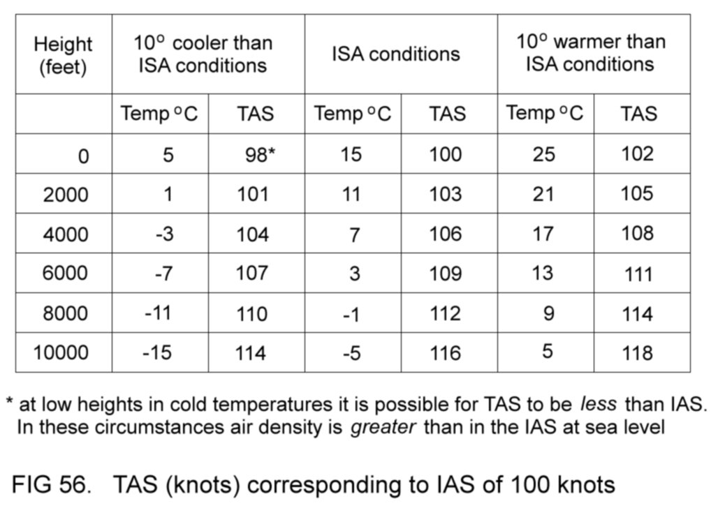
2.6.4.3
Groundspeed
As has just been
explained, the actual speed at which the aircraft
moves through the air is its TAS, which can be calculated by applying
density error correction to the IAS. If the air is stationary with
respect to the ground, then the aircraft's speed over the ground -
its groundspeed
(GS) - will equal its TAS. If, however, the air is moving over the
ground - in other words, if there
is a wind blowing - then the GS may differ from the TAS.
As an example, suppose
that a 20-knot wind is blowing. If an aircraft
whose TAS is 100 knots is flying into the wind then its GS will be 80
knots. Conversely, if it turns and flies in the same direction as the
wind then its GS will be 120 knots. Figure 57 represents these two
situations.
Aerodynamically, GS has
no significance; its importance lies primarily
in navigational planning.

2.6.5 The
altimeter
The altimeter registers
height. It makes use of the phenomenon already
mentioned that as height increases, the atmosphere's static pressure
becomes less.
Figure 58 is a schematic
representation of an altimeter.

The capsule is made from
thin metal and is evacuated of air. It is
fixed to the case of the instrument. A tapping from the static tube
(from the pressure head) leads into the case. Thus the outside of the
capsule experiences local static pressure.
The static pressure
acting on the evacuated capsule would cause it to
collapse, were it not for the metal spring which exerts a pull force on
the capsule, maintaining its shape - the effect of the spring balances
the effect of the air pressure.
With increasing height,
the static pressure in the case becomes less
and so the spring pulls the capsule into an expanded position, as
shown, greater height causing greater capsule movement. The movement
is registered on a scale calibrated in feet, the foot
being the
standard unit of height.
In modern altimeters the
capsule movement is geared to drive three
pointers, one indicating hundreds of feet, another thousands of feet
and the third tens of thousands of feet.
Figure 59 shows the
presentation on the instrument panel.

The tens of thousands of
feet pointer is often modified into the form
of indicator shown. At zero height indicated, the area revealed by the
window is blank. As height increases, a white-painted area comes more
into view in the window, the edge of the white area indicating the tens
of thousands of feet.
In Figure 59 the
altimeter shows a height of 4650 feet. Figure 60 shows
an indication of 8800 and Fig 61 shows 12000 feet.
The altimeter
indications are subject to various errors, which will be
described later.
2.6.5.1
Pressure datum
setting
When measuring height, a
datum is necessary for reference. In cruising
flight, the altimeter is usually made to indicate height above sea
level. But
the pilot of an aircraft flying in the
vicinity of an airfield may require the altimeter to register height above the
level of the airfield.
As an example, consider
an aircraft flying over an airfield, as
represented in Figure 62. The airfield is 500 feet above sea level.

Depending upon his
preference the pilot will want the altimeter to read
either 1000 feet (above airfield level) or 1500 feet (above sea
level). The altimeter must therefore have the capability of being
adjustable
to be able to achieve both requirements.
The adjustment mechanism
is controlled by the pressure
datum knob
(Figure
59) and makes
use of
the
decrease in pressure of the atmosphere
as height increases. As has already been stated, the pressure decreases
at the rate of 1 hectopascal (hPa) every 28 feet of height.
Suppose that, in the
example above, the sea level air pressure is 1020
hPa. Using the relationship just mentioned, we can calculate that the
air pressure at the airfield will be 1020 - (500/28) or 1002 hPa.
These pressure values of 1020 and 1002 hPa can be used as reference
datums. When the pressure datum in the altimeter is set to 1020 hPa
with the knob, the altimeter will register height above this
datum.
If
the setting is changed to 1002 hPa the altimeter will indicate height
above this new datum.
In the example in Figure
62, therefore, the aircraft's altimeter will
register 1500 feet when its pressure datum is set to 1020 and 1000 feet
when set to 1002.
The altimeter in Figure
59 is shown set to 1007, and those in Figures
60 and 61 to 983 and 1034 respectively.
2.6.5.2
Altimeter
terminology
Thus far in this book
the word 'height' has been used exclusively to
refer to vertical displacement from the earth. For air navigation
purposes, however, more specific terminology is required. In this
context:
(a) the word height
is used to describe vertical displacement from a
ground-based reference, usually an airfield;
(b) the word altitude
is used to describe vertical displacement above
sea level.
The phrases 'air
pressure at airfield level' and 'air pressure at sea
level' are respectively abbreviated into the international code forms
QFE and QNH.
In Figure 62 the
aircraft is said to have a height of 1000 feet on QFE
1002 hPa and an altitude of 1500 feet on QNH 1020 hPa.
It is apparent that care
must be exercised by the pilot when adjusting
his altimeter datum to ensure that the correct setting is used as
appropriate.
In certain navigational
circumstances the
altimeter datum is set to what is called the standard
setting,
which is
1013 hPa. When this setting is in use, the vertical displacement of the
aircraft is expressed in terms of flight
level (FL),
which is the
altimeter indication divided by a factor of 100. For example, an
indication of 4500 feet is referred to as FL 45.
2.6.5.3
Barometric error
At any particular
location the atmospheric pressure is constantly
changing, although usually not at a rapid rate. It also varies from one
location to another. Suppose that the aircraft in Figure 62 has
returned to the location shown after a period of several days, at an
indicated altitude of 1500 feet, and that the QNH at this location had
decreased from 1020 to 995 hPa.
If the pilot had
neglected to reset his altimeter to this new QNH, then
his
indicated altitude
of 1500 feet would be in error - it would be an
over-reading
of (1020-995) x 28 or 700 feet. The aircraft's true
altitude would therefore be 800 feet.
Of course, the QFE at
the airfield would now be 995 - (500/28) or 977
hPa. Use of the outdated value of 1002 hPa would again give a 700 feet
over-read
of height - an indicated
height of 1000 feet would in fact be
a true
height of 300 feet. Figure 63 clarifies the situation and shows
both the old and the new pressure datums.

Altimeter errors caused
by incorrect setting of the pressure datum are
called barometric
errors,
and they can be eliminated by appropriate use
of the setting knob. Thus the pilot returning to the location in our
example should set his altimeter either to 995 hPa to obtain correct
indications of altitude or to 977 hPa for correct indications of height
above airfield level.
From the foregoing
remarks, it is clear that here is another
reason,
besides that mentioned in 2.6.5.2, why the pilot must take every care
to ensure that his altimeter is correctly set. This is especially
important when flying from a region of higher QNH to one where the QNH
is lower, when failure to reset the altimeter will cause it to
over-read - to show that the aircraft is higher than it really is.
2.6.5.4
Terrain clearance
Note that use of QNH
does not enable the altimeter to register vertical
distance above the terrain. Even when set to QFE, the altimeter will
show vertical distance above only one selected area of terrain - the
airfield. For cruising flight the pilot sets the QNH. If the flight is
a long one, it is quite likely that this setting will need updating as
the aircraft travels from one location to the next, where the QNH may
be different.
It is clear, therefore,
that the pilot should be aware of the vertical
distance above sea level, or elevation,
of the terrain over which the aircraft flies. With this knowledge, it
is easy to assess the
vertical distance of the aircraft above the terrain - in other words,
its terrain
clearance
- if its altimeter is set to QNH. Information
about terrain elevation is to be found on the maps, or charts, used for
air navigation.
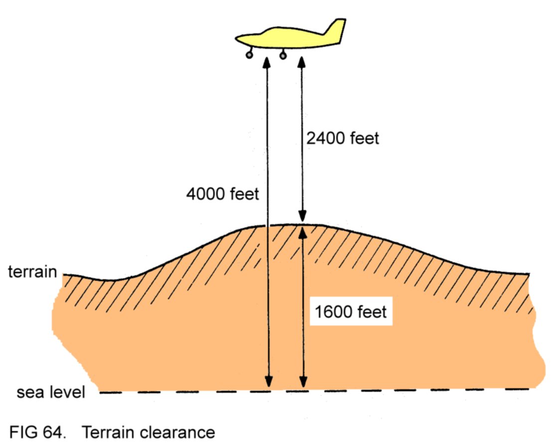
As an example, suppose
that the aircraft in Figure 64 is in cruising
flight. Its altimeter, set to QNH, indicates an altitude of, say, 4000
feet. The pilot will have determined, from consultation of the
navigation chart, that the elevation of the terrain at this location
is, say, 1600 feet. He will therefore know that the aircraft's
terrain clearance is 2400 feet.
Of course, using the
technique of visual flight, the pilot can see the
terrain below the aircraft and can verify that the clearance is
sufficient without having to consult his altimeter.
However, if the aircraft
were flying in cloud, with the pilot using
instrument flight technique, then he would be denied the sight of the
earth's terrain. In this case it would be necessary to choose a
cruising altitude safely above the terrain that would be encountered en
route and to ensure that the altimeter indication did not fall lower
than this altitude during flight.
2.6.5.5
Temperature error
Deviations of air
temperature from ISA conditions cause corresponding
deviations of pressure. In colder conditions, the air pressure at any
particular height is less than at the same height in the ISA. The
altimeter interprets the lowered pressure as an increased height - in
other words, it over-reads, showing the aircraft to be higher than it
really is. The converse is true in warmer conditions.
These discrepancies are
called temperature errors and they are of no
great significance except during instrument flight in very cold weather
(terrain clearance being the relevant consideration in this case).
2.6.5.6
Pressure error
and instrument error
The same considerations
apply to the altimeter as to the ASI (refer
back to 2.6.4.1). However,
the errors are insignificant and for all
practical purposes can be ignored.
2.6.5.7
GPS derived
altimetry
Many modern aircraft
incorporate Global Positioning System (GPS)
receivers in their navigation equipment. Some of these GPS receivers
can indicate altitude but it should be borne in mind that, although
their indications may be more accurate in absolute terms than those of
pressure altimeters, they are not used as primary reference since at
the present time vertical traffic separation procedures are based on
the indications of pressure altimeters.
2.6.6 The
vertical speed
indicator
The VSI shows the rate
at which the aircraft is climbing or
descending. Like the altimeter, it makes use of the decrease of
atmospheric pressure as height increases. The instrument is represented
schematically in Figure 65.

A tapping from the
static tube leads into the VSI case and then
branches into two tubes, one of which runs directly into the capsule.
The other tube leads into the body of the instrument via the metering
device, as shown. The metering device is merely a restrictive orifice
which retards any movement of air past itself.
When the aircraft is in
flight at constant height it is clear that the
inside and outside of the capsule experience the same pressure. In this
situation the capsule will be in its rest position and the pointer will
indicate zero, showing no climb or descent.
If the aircraft is now
made to descend, it will be flying into a
region of denser air, where the static pressure is obviously greater.
Whilst the inside of the capsule will experience this greater pressure
directly, the metering device will retard the inflow of the denser air
into the body and so the pressure experienced by the outside of the
capsule will be less than that inside.
Accordingly, the capsule will
expand, its movement being converted by the linkage to a pointer
indication of descent.
An opposite sequence of
events occurs if the aircraft is made to
climb. Note that the more rapid the climb or descent, the greater is
the delaying effect of the metering device and so the difference in
pressure inside and outside the capsule is more marked. This in turn
causes greater capsule movement, which makes the pointer move further
away from zero. In other words, the instrument indicates the rate of
climb or descent. The scale is calibrated in feet per
minute.
Figure 66
shows the presentation on the instrument panel. A climb of 500 feet per
minute is indicated.
The metering device is
so constructed that the VSI indications are
accurate regardless of height or air temperature. However, the
indications are
subject to the errors described below.

2.6.6.1
Lag
A period of a few
seconds is required for the metering device to
convert any change in static pressure into a pressure difference inside
and outside the capsule. Because of this, there is a corresponding
delay in the VSI indications - it takes a few seconds for the pointer
to settle on a steady reading. The delay is termed lag and is most
noticeable when abrupt changes occur in the rate of climb or descent.
Abrupt changes from
climb to descent and vice versa may even cause the
instrument to register in
the reverse sense,
albeit temporarily.
Consider the aircraft in Figure 67 which has just changed its flight
path from a rapid climb to a rapid descent.
Note that the VSI
indication at the start of the descent incorrectly
shows that the aircraft is still climbing.
It can be appreciated
that the VSI gives reliable indications
only
when the
indications are steady.

2.6.6.2
Pressure error
Any change in static
pressure is interpreted by the VSI as a climb or
descent. If the change is due to inconsistent sensing of static
pressure at the pressure head (which could be caused by a change in the
aircraft's speed, for example) then obviously the VSI indications may
be false. This pressure
error is
negligible in most light aircraft
because of the relatively gentle accelerations and decelerations that
are experienced.
2.6.7
Direction
The magnetic
compass
shows the direction
in which the nose of the aircraft is pointing, the reference for
direction being magnetic
north. At
any point on the surface of the earth, magnetic
north is the
direction in which the north-seeking end of a freely-suspended
magnetised rod aligns itself, acting under the influence of the earth's
natural magnetic field. At most locations this direction differs from
true
north,
which is the direction in which the earth's geographic
north pole lies. The difference between the two directions is termed
variation,
and in European areas is not great (Figure 68).

Magnetic
direction
is measured as angular displacement from
magnetic north. In
air navigation, direction is expressed in terms of degrees (°).
The three directions
shown in Figure 69 are 008°M, 063°M and 251°M. 'M'
denotes magnetic direction.
In
this nomenclature, the magnetic cardinal
directions
north, east, south
and west are respectively expressed as 360°M (rather than 000°M),
090°M, 180°M and 270°M. The magnetic inter-cardinal
directions
north-east, south-east, south-west and north-west are respectively
expressed as 045°M, 135°M, 225°M and 315°M.
The direction in which
the nose of the aircraft points is called its heading. The
aircraft
in Figure 70 have headings of 080°M and 305°M.
2.6.8 The
magnetic compass
The aircraft's heading
is indicated to the pilot by the magnetic
compass, which is shown schematically in Figure 71.
The
magnets are
attached to the circular card
and the whole assembly is
suspended below a pivot
which is fixed to the case. The assembly can
thereby rotate independently of the case. On the card are marked the
heading indications.

The case features a
glass window
so that the card can be seen from outside. A vertical lubber line in
the middle of the window is the reference against which the heading
indication is read. (For clarity of marking on the card, the final zero
is omitted from the indications, as is the first zero on the
indications of 030° and 060°. The cardinal directions are marked as N,
E, S and W.)
The magnets align
themselves with their
north-seeking ends pointing in the direction of magnetic north. Thus
the card is held in one fixed orientation, regardless of the
orientation of the case (which is secured to the airframe structure).
The case is filled with
alcohol, the liquid serving two purposes:
(a) by helping to
support the magnet
assembly (in the same way that water supports ships), it minimises the
friction at the pivot, making the
compass more sensitive;
(b) it damps down
oscillations of the
magnet assembly, conferring steadiness to the compass indications.
In
Figure 71 the aircraft has a heading of 360°M, and in Figure 72,
270°M. As an aid to understanding, the symbol shown on top of the case
represents the aircraft within which the compass is mounted.
The
compass is located in a suitable position in the cabin, where it is
easily visible. Figure 73 shows various heading indications as the
pilot sees them.


2.6.8.1
Compass errors
Objects made of
ferrous metals (iron and steel) distort the earth's natural magnetic
field in their vicinity. Aircraft components made of these metals,
such as the engine, may therefore cause the compass to give erroneous
indications (since the magnets will align themselves with the distorted
field). A similar effect is caused by electrical equipment, which when
switched on may set up weak magnetic fields, these fields locally
distorting the earth's field. Discrepancy of heading indication
resulting from such disturbances is called deviation, and can
be
minimised (but not completely eliminated) by:
(a) locating the compass
as far as possible from electrical equipment
and components made of ferrous metals;
(b)
suitable adjustment of the correction mechanism built into the compass.
(The correction mechanism contains tiny magnets which set up fields
helping to cancel out those tending to disturb the compass.)
The
residual deviation is usually less than 2° - it varies according to the
aircraft's heading - and can be ignored for all practical purposes.
Periodically the compass is checked, or swung, by qualified
technicians, to verify that its deviation is not excessive.
It goes
without saying that, during flight, objects made of ferrous metals
(such as tools) must never be stowed near to the compass installation,
since these might cause excessive deviation.
The various forces
which act on the aircraft when it is flying in a banked attitude, and
during acceleration and deceleration, upset the magnet assembly, with
the result that the compass gives incorrect indications. Even gentle
flight manoeuvres may cause considerable errors.
For this reason the
compass can be relied upon to give correct heading information only
when the aircraft is flying at
a constant speed with its wings level.
Another
problem arises if the aircraft encounters turbulent air, when the
compass card will oscillate irregularly (despite the damping effect of
the alcohol), making it difficult for the pilot to assess the
aircraft's heading.
2.6.9
The gyroscope
A gyroscope (usually
abbreviated to 'gyro') is an object designed to make use of the
physical phenomena associated with rotational motion. Typically, the
gyro comprises a metal wheel mounted in a suitable housing. The wheel
is made to spin at high RPM (Figure 74).

Three of the flight
instruments - the attitude indicator (AI), the
direction indicator (DI) and the turn-and-balance indicator (TBI) -
incorporate gyros, each instrument utilising one of the two most
important gyroscopic properties, which are:
(a) rigidity
- the natural tendency of the gyro to resist changes in its orientation;
(b) precession
- the resulting motion of the gyro when a disturbance is forced upon it.
In the flight
instruments mentioned above, the gyros are made to rotate
by one of two means, as described below.
2.6.9.1
The
suction-driven
gyro
The gyro is mounted in a
metal case, from which the air is sucked by a
suction pump driven by the aircraft's engine. Replacement air is
allowed to enter the case through a filter, whose purpose is to remove
foreign matter. The air is then ducted to the gyro where it impinges
upon special indentations on the periphery, making the gyro rotate
(Figure 75).

The gyro will rotate
steadily so long as suction is maintained. Failure
of the engine or of the suction pump, or serious leaks in the suction
tubes, will result in the gyro slowing down and stopping - the
associated flight instrument will then become inoperative.
A gauge mounted on the
instrument panel measures the strength of the
suction. The aircraft manufacturer will specify the range within which
the reading on the gauge should lie when the engine is running
normally. A reading outside this range implies a fault in the suction
system and is a warning to the pilot that the suction-powered flight
instruments can no longer be depended upon to give reliable information.
2.6.9.2
The
electrically-driven gyro
The electrically-driven
gyro is merely a modified electric motor, in
which the metal wheel incorporates the motor's moving coil. The
assembly will rotate whenever electric current is
supplied to the coil.
Failure of the current
supply will cause the gyro to slow down and
stop, rendering the associated flight instrument inoperative.
2.6.9.3
Flight instrument
power supplies
In light aircraft the
usual arrangement is for the AI and the DI to
be suction-powered and the TBI to be electrically-powered, so that at
least one of the three instruments remains operative after failure of
one of the power supplies.
2.6.10 The
attitude
indicator
The AI indicates the attitude
of the aircraft and is referred to by
the pilot when the earth's horizon is obscured. Its gyro is mounted in
housings, or gimbals,
in such a way that its orientation is totally
independent of the aircraft's attitude.
The gyro is so designed
that, whenever it is spinning, it orientates
itself with its axis vertical with respect to the earth's horizon. In
this state the gyro is said to be erect.
(Erection usually takes several
minutes from the moment the gyro starts to rotate.) Figure 76
illustrates.

The gyro's rigidity
maintains it in this orientation regardless of the
attitude of the aircraft. Attached to the gimbal arrangement by
pivots, the horizon
display
(see Figure 77) is held level with respect
to the earth's horizon by the gyro - the horizon display is said to
be gyro-stabilised.
The diagram shows the presentation of the AI on the instrument panel.
The attitude
datum
(which symbolically represents the aircraft
viewed from behind) is fixed inside the glass face of the
instrument, and so change of aircraft attitude is indicated by
change of position of the horizon display relative to the attitude
datum.
The AI indication in Figure 77 corresponds to the cruising flight
attitude shown in Figure 51
. Indications corresponding to other
attitudes are shown in
Figure 78.
2.6.11 The
direction
indicator
It has been previously
mentioned that the magnetic compass heading
indications are unreliable during flight manoeuvres and unsteady in
turbulence. These drawbacks are overcome in the gyro-stabilised DI.
When it is spinning, the
gyro in the DI orientates itself with its axis
pointing in a fixed direction. In this state it is considered erect
(Figure 79).
The gyro is mounted in
gimbals which allow its rigidity to maintain it
in the fixed directional orientation regardless of the aircraft's
heading (in the same manner that the compass magnets hold one fixed
orientation). The gimbal arrangement is geared to drive the indicator
card
(Figure 80), so that change of heading causes the
card to rotate
behind the heading datum.
The diagram shows the presentation on the
instrument panel, with the DI indicating 360°M. A heading of 255°M is
indicated in Figure 81.


Of course, although the
DI gyro is held in a fixed directional
orientation by its rigidity, this orientation is random - when erect,
the gyro's axis might point in any direction. A means is therefore
provided for orientating the axis correctly with respect to our chosen
directional datum - magnetic north. When the synchronising
knob
is
pushed in and turned, the gimbal assembly, and therefore the card, can
be rotated so that the heading datum shows the same indication as the
magnetic compass. Releasing the knob frees the gimbal assembly so that
the card is again acting in its gyro-stabilised mode. The DI is now
said to be synchronised
with the compass
and will indicate heading in
terms of magnetic direction. Furthermore, the indications will be
correct during manoeuvring flight and steady in turbulence.
2.6.11.1
DI errors
Ideally, once the DI has
been synchronised with the compass and the
knob released, it should remain synchronised indefinitely.
However, a complication
arises from the fact that the gyro's fixed
directional orientation makes no allowance for the effect of the
rotation
of the earth, which causes the DI indication to become increasingly
incorrect with the passage of time. Fortunately this effect can be
offset by an internal adjustment device within the DI. The adjustment
device rotates the gyro axis at such a rate that the discrepancy is
eliminated. It is set according to the geographical area within which
the aircraft is expected to fly. If the aircraft is moved to a
different area further north or south, the adjustment device will need
to be reset to allow for the difference in the effect of the earth's
rotation. Resetting is only required when the change of location is
considerable. For example, it would not be worthwhile for an aircraft
based in the UK to have its DI readjusted for flights in continental
Europe.
A further problem is
that the frictional forces in the gimbal assembly
slowly change the directional orientation of the gyro axis. In other
words, they make the gyro precess.
If the adjustment device
described above has been correctly set and if
the internal friction forces are not great, then the discrepancy in
heading between the DI and the magnetic compass after synchronisation
should not increase rapidly. (A rate of change of more than 20° per
hour would be considered excessive.)
In practice, therefore,
normal procedure is to synchronise the DI
before take-off, and then to re-synchronise during flight at intervals
of 15 minutes or so.
2.6.11.2
The
self-synchronising DI
In aircraft fitted with
more sophisticated equipment the conventional
DI is sometimes replaced by a self-synchronising model. A description
of the instrument is beyond the scope of this book. The operating
principle is that an electrically-powered compass system keeps the DI
synchronised with respect to magnetic north, relieving the pilot of the
requirement to synchronise manually. The magnetic compass is usually
retained as a back-up in case of failure of the electrically-powered
system.
2.6.12
Toppling
With most designs of AI
and DI the gimbals give their gyros
independence of orientation only within certain physical limits of
gimbal movement. These limits will not be reached during normal flight
manoeuvres. However, extremes of attitude (such as may occur during
aerobatics) may well bring the gimbals to their limiting positions.
When this happens the gyros are made to precess by the
disturbing
forces, usually undergoing rapid oscillatory change of orientation. A
gyro behaving in this manner is said to be toppled and its
associated
flight instrument will, of course, be inoperative. Random movement of
the horizon display (in the AI) and rapid rotation of the indicator
card (in the DI) are the usual symptoms of toppled gyros.
Once the aircraft has
returned to a level attitude, a period of
several minutes may be required for the AI to re-erect itself, during
which time its indications should be disregarded. The DI can be
re-erected immediately by pushing in and releasing the synchronising
knob. (In practice the knob is pushed in and rotated to resynchronise
the DI with the compass, and then released again.)
2.6.13 The
turn-and-balance indicator
It is universal practice
for the turn indicator and the balance
indicator to be combined so far as instrument panel presentation is
concerned - the TBI is therefore two separate instruments in one
presentation.
2.6.13.1
The turn
indicator
The turn indicator
incorporates a gyro which utilises the phenomenon of
precession rather than rigidity. As its name suggests, the instrument
shows when the aircraft is turning - in other words, when the heading
is changing.
The gyro is mounted with
its axis running from left to right relative
to the aircraft. In straight flight it is held in this position by
springs attached to its gimbal. If the aircraft turns to the left, the
ensuing forces acting on the gyro make it precess - it tilts against
the restoring effect of the springs. A turn to the right makes the gyro
tilt the opposite way (Figure 82).

As soon as the aircraft
stops turning the springs restore the gyro to
its central position. The movements of the gyro are geared to the turn
indicator. Note that the more rapid the turn, the greater the
precession and the more the gyro tilts against the effect of the
springs. Thus the instrument indicates the rate of turning. Figure 83
shows the instrument panel presentation. The indicator is central,
showing no turn.
In a rate 1 turn, the aircraft
heading changes at the rate of 3° per
second. To turn from 090° to 270° would take 60 seconds. In a rate 2
turn, the heading changes at the rate of 6° per second. To turn from
090° to 270° would take 30 seconds.
Figure 84 shows
indications of a rate 1 turn left and a rate 2 turn
right. Failure of the power supply to the instrument will result in the
gyro stopping, in which case the indicator will remain central even
when the aircraft is turning.
2.6.13.2
The balance
indicator
The balance indicator is
the simplest of the flight instruments. It
consists merely of a sealed curved glass tube filled with liquid in
which a solid ball is free to move (Figure 85).
The disposition of the
various forces (including gravity) acting on the
aircraft during flight determines the position of the ball in the tube.
When the disposition of
these forces is
such that the balance indicator ball lies within the two central
markings, the aircraft is said to be 'in balance'. Unbalanced flight
is indicated by displacement of the ball from the central position -
the greater the unbalance, the more the ball is displaced. Figure 86
illustrates.

The pilot uses his
controls to keep the ball centred since unbalanced
flight is inefficient - it results in the aircraft generating more
drag than is necessary. (Occasionally, when extra drag is desired for
modification of the aircraft's flight path, the pilot may deliberately
fly the machine out of balance. In this situation, of course, the ball
in the balance indicator will be displaced from the central position.)
The purpose of the
liquid in the tube is to help to damp out
oscillations of the ball during manoeuvring flight. Figure 87 shows the
instrument panel presentation of the complete TBI.

2.6.14
Electronic flight
instrument systems
Many newer light
aircraft are fitted with electronic flight instrument systems (EFIS),
in which the mechanical sensors and indicators described above are
replaced with electronic components.
The operating principle
is
that the inputs from the pitot pressure and static pressure lines are
directed to electronic detectors. Aircraft attitude, magnetic
heading and rate of turn are sensed by electronic components. After
processing, the data
generates a display on a liquid crystal display (LCD) screen on the
instrument panel. Figure 88 shows a representation of an EFIS display.

In Figure 88 the
instantaneous
readouts are shown against scrolling background scales. In addition to
a numerical readout, vertical speed is also indicated by a variable
length arrow. The reversed colouring on the numerical readout is to
prevent any confusion with altitude indication. Airspeed trend is also
shown pictorially (red 'down' arrow for decreasing IAS and green 'up'
arrow for increasing).
Compared to mechanical
instruments EFIS installations have several
advantages:
(a) greater reliability
and reduced maintenance costs;
(b) lighter and more
compact construction;
(c) automatic
synchronisation of the direction indicator;
(d) elimination of
requirement for engine-driven suction pump.
2.7 THE
PILOT'S CONTROLS
Figure 89 shows what
might be a typical layout for the forward end of
the cabin of a modern single-engined light aircraft equipped with a
fixed-pitch propeller and fixed (non-retractable) landing gear.

It is usual for
interconnected dual controls to be fitted so that the
machine can be controlled from either of the front seats, although the
flight instruments
(Figure
46)
are positioned on the left of the
instrument panel
since the left seat is the position from which the aircraft is flown
when only one pilot is on board.
2.7.1
The flight controls
The flight controls -
the ailerons, elevators and rudder - are
activated by the control wheel and the rudder pedals, as described
below.
2.7.1.1
The ailerons
The control wheel is
connected to the ailerons by cables or rods.
Rotating the control wheel to the left raises the left aileron and
lowers the right aileron, and vice versa. The control wheel is
progressive in its operation - greater control wheel movement results
in greater aileron displacements. When the control wheel is in its
central position the ailerons are undisplaced (Figure 90 and Figure
6
).

2.7.1.2
The elevators
The control wheel is
also connected to the elevators by cables or rods.
Pulling the control wheel backwards (towards the pilot) raises the
elevators, and vice versa. The control wheel is progressive in its
operation. When it is centralised the elevators return to their
undisplaced position (Figure 91).
2.7.1.3
The rudder
The rudder pedals are
connected to the rudder by cables or rods.
Pushing the left pedal forwards deflects the rudder to the left;
pushing the right pedal forwards deflects the rudder to the right. The
pedals are progressive in their operation. When they are centralised
the rudder returns to its undisplaced position.
In most tricycle landing
gear aircraft, the rudder pedals are also
linked either rigidly or via springs to the nosewheel steering
mechanism, for steering the machine during ground manoeuvring.
Pushing forwards the left pedal turns the nosewheel to the left, and
vice versa. Figure 92 illustrates these two functions of the rudder
pedals.

A third function of the
pedals is to apply the mainwheel brakes. The
pilot pushes the upper portion of the appropriate pedal with his toes
to apply the associated brake. When these 'toe brakes' are
not in use,
the pilot drops his feet to the lower parts of the pedals.
2.7.1.4
Control locks
Whenever the aircraft is
parked in strong winds, an internal locking
device is used to hold the control wheel firmly in its central
position. Any tendency for the wind to move the ailerons and elevators,
which might lead to them being damaged if violent movement occurred, is
thus prevented. A separate lock secures the rudder pedals, unless the
pedals are linked to the nosewheel, in which case movement of the
rudder is prevented by the fact that the nosewheel is in contact with
the ground and will resist turning to the left or right.
Common sense dictates
that, whenever the aircraft is to be left parked
unattended for any length of time, the control lock(s) should be
employed.
2.7.2
The flaps
In the layout shown in Figure
89,
the flaps are lowered and raised
mechanically by pulling up or lowering the flap lever, the linkage
incorporating a ratchet so that intermediate selection(s) of flap
position between fully up and fully down are possible (Figure 93 and Figure
5).

As an alternative, many
aircraft feature electrically-operated flaps.
When the control switch (usually located on the instrument panel) is
pushed down, the electric flap motor lowers the flaps; when the
switch is pushed up the motor raises the flaps. With the switch in its
central position no current is supplied to the motor and the flaps are
retained at whatever position they happen to be. Thus intermediate
selections are possible.
2.7.3
The elevator trim
tab
The control for the
elevator trim tab is usually in the form of a
wheel, to which the tab is connected by cables. When this 'trim wheel'
is rotated upwards and forwards the tab is displaced upwards; rotation
of the wheel backwards and downwards displaces the tab downwards. The
control is progressive in its operation. When the wheel is released the
tab is retained in whatever position it happens to be. Centralising the
wheel brings the tab back to its undisplaced position (Figure 94).

If the aircraft features
aileron and rudder tabs adjustable in flight,
they are controlled by similar trim wheels.
2.7.4
The engine controls
The engine controls are
usually grouped together in a low central
position on the instrument panel, as in the example in Figure
89.
The throttle is opened
by pushing its lever forwards, and closed by
pulling the lever backwards.
If it is required that
the throttle lever retains any set position, the
friction control is tightened. Otherwise, it is loosened to permit easy
movement of the lever.
The mixture control is
set to 'rich' by pushing its lever forwards, and
to 'weak' by pulling it backwards. On many designs the mixture control
lever is used to stop the engine after flight by moving it to its
rearmost position. The lever is then in the 'idle cut-off' position,
and
the fuel supply to the nozzle in the carburettor is completely cut off.
The carburettor heat
control is set to 'off' by pushing its lever
forwards and to 'on' by pulling it backwards. Note that the throttle
and mixture control levers are progressive in their operation, whereas
the carburettor heat control should be selected either 'on' or 'off'.
The magneto switches are
usually amalgamated into one key-activated
control which is also used to energise the electric starter motor for
engine starting. Figure 95 shows a typical arrangement.
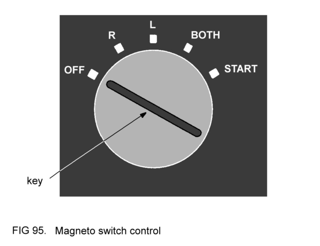
When the key is at the
OFF position both magnetos are switched off. At
the R position the right magneto is on, and the left off, and vice
versa at the L position. At the BOTH position both magnetos are on.
For engine starting, the key is turned fully clockwise to the START
position. (In this function the control is similar to that of a car.)
2.7.5
Electrical services
It is usual design
practice to group together the various switches for
the electrical services (including the master switch) on the
instrument panel. In
Figure 96 the switches are of the 'rocker' type - each is selected on
by pushing in its top portion and off by pushing in its lower portion.
Similarly, the fuses,
spare fuses and circuit-breakers are usually
grouped together.

2.7.6
Seats and harnesses
Both of the front two
seats are adjustable
forwards and backwards, and in some designs, up and down. Correct
adjustment of his seat to suit the individual pilot is important - he
should be able to reach comfortably all of the various controls. It is
equally important to ensure that the seat is firmly locked in
position
once it has been adjusted.
Restraining harnesses
are provided for
every seat in the cabin. The front two seats are usually equipped with
both lap straps and upper harnesses. These latter are normally of the
inertial reel type, enabling freedom of movement when reaching for
controls, but locking in the event of impact. For take-off and landing
full harness should be worn, with the lap straps tight (but not
uncomfortably so). During cruising flight most pilots prefer to retain
at least the lap straps in position to guard against the possibility of
being thrown around in turbulent air.
2.8
AVIONICS
We shall look
at three examples of avionics (aviation
electronic equipment) often found in
modern light aircraft.
2.8.1
The COM radio
Although there is no
mandatory requirement, most modern light aircraft
are fitted with communications (COM) radio, since lack of
this equipment limits the operational flexibility of the aircraft, and
may preclude entry into certain regions of airspace.
The COM radio provides
air-to-ground, ground-to-air and, if needed,
air-to-air speech communication. It operates in the Very High Frequency
(VHF) range. At the present time, the frequencies (or channels) available
lie in the range 118 to 137 Megahertz
(MHz). The COM radio is the means by which the pilot communicates with
Air Traffic Control (ATC) when required.
The aircraft's COM
equipment consists primarily of a transceiver
(transmitter-receiver) located in the instrument panel. Figure 97 shows
a typical installation.
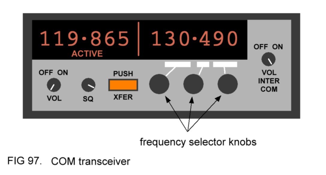
The frequency
selector knobs allow any of the COM frequencies
to be selected. Note that the frequency thus selected
is not
the active one, which is the frequency displayed on the left side of
the transceiver. Pressing the transfer (XFER) button will swap the two
frequencies so that the last selected frequency is now active. This
arrangement confers two advantages:
(a) the next anticipated
frequency can be preselected, reducing pilot
workload;
(b) in the event contact
can not be established on the new frequency,
the previous frequency can be quickly reselected.
The transceiver will
both transmit
and receive
on the active frequency.
A headset
worn by the pilot is used in conjunction with the
transceiver. The headset consists of two earphones to one of which is
attached a boom-mounted microphone. A lead from the headset plugs into
jack
points
located at a convenient position on the instrument panel
(Figure 98).

To transmit speech, the
pilot presses down the transmit
button
mounted
on the control wheel (the button is connected to the transmitter) and
then speaks into his microphone, held adjacent to his mouth by the
boom. When his message is finished he releases the transmit button.
Messages from the
receiver are heard in the earphones. Note that
whenever the transmitter is in use, the receiver is automatically
deactivated. If the pilot forgets to release his button after
transmission, he will not be able to hear incoming signals.
The volume
control
(Figure 97) is used to control the volume of
reception heard in the earphones. (It does not control the strength of
transmission - this cannot be varied by the pilot.) The squelch
control
adjusts the sensitivity of the receiver. When reception is strong the
control can be turned down, reducing sensitivity and hence eliminating
background noise. If reception is weak the control is turned up,
increasing sensitivity (although this will bring the disadvantage of
more background noise).
If there are two pilots
in the aircraft, conversation between them is
facilitated by the use of the radio's built-in intercommunication
('intercom') system. When the headsets are worn and the intercom is
switched on, conversation is relayed from both microphones to both
pairs of
earphones. Note that the
transmit button is not used for intercom.
The aerial
for the transceiver is usually located externally on the
fuselage.
2.8.2 The
transponder
The
transponder is an electronic installation fitted to many light aircraft
that can send coded radio signals to ATC. When required, ATC will ask
the pilot to 'squawk' a specific 4-digit code, which is achieved by the
pilot selecting these digits on the transponder (Figure 99). In this
way ATC can identify the individual aircraft on their radar screens,
which pictorially show the geographic locations of all the aircraft
under their control.

The push-button controls
allow the pilot to select the following modes:
OFF -
transponder unpowered;
STBY -
transponder in standby mode, electrically powered but not sending or
receiving signals;
ON -
transponder sending selected squawk;
ALT-
transponder sending selected squawk and aircraft altitude data;
IDENT
- transponder momentarily sends identification signal when requested by
ATC to emphasise the aircraft position on the ATC radar screen.
2.8.3
The GPS map display
Many light aircraft are
fitted with Global Positioning System (GPS)
equipment, which operates in a similar manner to that found in cars,
except that the display is usually set to show a plan view of the
aircraft geographic location in the form of an electronic map. Besides
the features usually to be found on conventional maps, the aircraft's
GPS display will show airfields and the boundaries of regions of
airspace where specific rules apply to aircraft flying within them.
2.9
THE CHECKLIST
The reader will
appreciate the importance of checking that the aircraft
and all its components and controls are serviceable before an
intended flight - it is clearly better to discover any
unserviceabilities while the machine is still on the ground.
Again, the pilot must be
able to operate the various controls in the
correct manner and sequence.
Both of these
considerations explain the need for a checklist. The
checklist usually takes the form of a flip-card booklet and contains
instructions advising the pilot of the correct sequence of actions that
must be performed at appropriate times before, during and after flight,
in order to operate the aircraft safely and efficiently.
The checklist is usually
divided into two sections, the first covering
normal
operating
procedures.
The second section, emergency
procedures,
lists the sequence of actions that must be carried out to deal with
various emergency situations should they arise.
In some checklists brief
technical details of the aircraft may be
included, examples being loading limitations and fuel consumption rates.
Most pilots who fly
regularly take the trouble to memorize certain
parts of the checklist, such as the various actions that must be
performed during flight, and the more important of the emergency
procedures. In this latter case, use of memorized procedures rather
than reading from the checklist will allow the pilot to deal
with the situation more expeditiously.
Note
The descriptions in this
Section are generally representative of light
aircraft technology as it is at the present time. It must be
emphasised that individual designs of aircraft that the reader may
encounter may well differ from the examples given here to a lesser or
greater extent.
The source of technical
information for any aircraft is its Flight
Manual.
3 DETAILED THEORY OF FLIGHT
In
this Section the basic theory of flight will be expanded and the forces
introduced in Section 1 will be analysed in greater detail.
Additionally, some applications to practical flight will be mentioned.
3.1
WEIGHT AND CENTRE OF
GRAVITY
It
will be recalled that the centre of gravity (CG) of an aircraft was
defined as the point from which the single equivalent total weight
force acted (Figure
2)
.
3.2
LIFT
Lift is generated by the
aircraft's wings
and is derived from two features of the wing, namely its angle of
attack and
its shape.
3.2.1
Angle of attack
Consider a
flat plate moving through the air at a shallow angle. The effect of the
motion is to cause an airflow past the plate, as shown in Figure 100.

The
angle at which the plate meets the airflow is called the angle of
attack.
Because of
the air pushing underneath, the plate experiences a force which
attempts to move it upwards and backwards. This force is called the
total
reaction
(R). It can be considered as split, or resolved, into
two separate forces, or components,
one acting upwards, the other
acting backwards, opposing the direction of motion of the plate.
The upward-acting
component is lift
(L) and the backward-acting
component is drag
(D), as shown in Figure 100.
It
will be appreciated that, when the angle of attack is zero, no lift
will be generated (although, of course, there will be some drag).
3.2.2
Wing shape
The
flat plate in Figure 100 is not an efficient producer of lift. Far
better
is the typical wing aerofoil shape, shown in Figure 101 with the
airflow
pattern that surrounds it when it is moving through the air and
inclined at a small angle of attack.

Not only does this shape
generate more lift than the flat plate under the same conditions, but
its drag is less. Notice that, in Figure 101, a line has been drawn
from
the leading edge of the wing section to the trailing edge. This is
called the chord line
and is the reference for assessing the angle of
attack of the wing. Notice, too, that the total reaction acts from a
point on the wing about a third of the way back from the leading edge.
How
does the aerofoil shape generate lift? As it moves through the air the
curved shape speeds up the flow over the upper surface, which
causes the air to lose some of its natural pressure, since the laws of
physics demand that the sum total of its energy (that is, its energy of
movement and its pressure energy) must remain constant. In other words,
wing motion through the air creates a partial vacuum above it. The air
at normal pressure underneath the wing therefore exerts a push force
upwards and this is the lift force that keeps the aircraft flying. In
contrast to the flat
plate, the wing will generate lift even when its angle of attack is
zero. If the wing is then inclined to the airflow at a shallow angle of
attack (as in Figure 101) its lift will increase further, as would be
expected.
Notice
that the airflow, as it approaches the leading edge of the wing, starts
to move upwards, attracted as it is towards the area of reduced
pressure. Because of this, the air just ahead of the leading edge is
termed upwash.
After the airflow has passed the wing, it moves
backwards and slightly downwards. Accordingly, the air behind the wing
is termed downwash,
and its significance will become apparent later on.
As
a practical demonstration of lift and downwash, suspend a teaspoon
adjacent to the flow of water from a tap and then move it closer until
the back of the spoon just touches the flow. The spoon will then be
pulled into the stream of water, deflecting it as shown in Figure 102.
The pull is, of course, analogous to lift, whilst the deflected water
corresponds to downwash. Compare the shape of the teaspoon
bowl with the wing section in Figure
101.

3.2.3
Factors affecting
lift
3.2.3.1
Angle of attack
As
already mentioned, a wing will generate lift even when its angle of
attack is zero. However, for a particular speed of airflow, an increase
in angle of attack has the effect of increasing the lift, until
an angle of about 15° is reached. At or above this angle, called the
stalling angle, the airflow past the wing becomes turbulent and no
longer follows the shape of the wing. This state of affairs is shown
in Figure 103.

This break-up of the
airflow destroys to a large extent
the lift-generating ability of the wing, although a certain amount of
lift is still generated by the 'inclined flat plate' effect.
However, if the angle of attack is increased further, even this lift
becomes reduced. The stalling angle differs according to the actual
shape of the aerofoil section but, for most light aircraft wings, is
about 15°.
In summary, a graph
illustrating the relationship between
lift and angle of attack is shown in Figure 104. Remember that the
graph
assumes that the speed of the airflow is constant.

3.2.3.2
Speed
For a particular angle
of attack, a wing will generate more lift the
faster it moves through the air. Mathematically, the lift generated is
proportional to
the square of the speed - the wings of an aircraft flying at 200 knots
will generate four times
as much lift as they do when the aircraft
flies at 100 knots, assuming that the angle of attack is the same at
both speeds.
3.2.3.3
Aerofoil shape
It has already been seen
that the wing
shape contributes considerably to its lift-generating ability. The
aerofoil shape shown in Figure 101 is
typical of that utilised by many light aircraft with cruising speeds
of about 100
knots.
If it were necessary to
design an aircraft for
low-speed flight, some means would have to be found to ensure that the
wings were able to generate enough lift for the aircraft to fly. One
solution would be to position the wings on the airframe so that they
met
the airflow at a high angle of attack. However, as will be
explained later, this design would incur an unacceptably high drag
penalty. A more efficient means of improving the lift-generating
ability at low speeds would be the use of a thicker, more highly-curved
aerofoil shape.
Conversely, an aircraft
designed to cruise at speeds much higher than
100 knots would
employ a thinner, less highly-curved aerofoil shape, this
shape being more efficient at these
speeds. Note that the curvature of the wing is sometimes
referred to as its
camber.
Consider again the
average light aircraft, with its 100
knot cruising speed. For take-off and landing, it would be highly
desirable to be able to fly at much lower speeds, so that long
runway lengths would not be required. Would it not be advantageous if
it were somehow possible to change the shape of the wings so that they
were more highly curved? Now
refer back to
Figure
5.
One reason for incorporating flaps into the wing structure is now
evident - it is to improve the lift-generating ability of the wings at
low speeds by conferring greater curvature to their shape.
3.2.3.4
Wing area
The
relationship is as would be expected. Other things being equal, the
greater the area of an aircraft's wings, the greater is the lift
generated.
3.2.3.5
Air density
Not surprisingly, a wing
moving
through less dense air generates less lift than it does when moving at
the same speed and angle of attack through more dense air.
3.3 TAIL
DOWN-FORCE
As
previously mentioned, the tailplanes together generate the tail
down-force. To understand how this force is generated, it is merely
necessary to visualise the airflow past the aircraft (Figure 105).

Notice
that the downwash strikes the tailplanes at an angle. If the diagram is
now turned upside-down, it will be appreciated that the tailplanes will
generate a force in the same manner as do the wings. Figure 105 shows
the force resolved into a downward-acting component, which is the tail
down-force, and a backward-acting component, which is obviously drag.
3.4 DRAG
Drag is the force acting
on an object in opposition to the
direction
of its motion as it moves through a fluid and arises from the
resistance
of the fluid to the disturbance caused by the object's
passage. Every part of an aircraft in flight that is exposed to the
airflow generates drag. We have already come across two examples - the
wings and the tailplanes.
3.4.1
Factors affecting
drag
3.4.1.1
Shape
In
Figure 106, two objects are moving through the air at the same speed.
One is a sphere, the other a tear-drop shaped streamlined object having
the same
cross-sectional area.
The pattern of the airflow around
each
object is shown.

The sphere disturbs the
airflow more than does the
streamlined object, as evidenced by the greater turbulence of its wake.
Because of this, the drag generated by the latter is considerably less
than that from the former. In fact the streamlined object generates
only about one tenth of the drag generated by the sphere - a
considerable reduction.
Making use of the
principle of streamlining, the designer therefore
minimises the drag generated by his aircraft.
3.4.1.2
Speed
The
faster an object moves through the air, the more drag it generates.
Mathematically, the drag generated is proportional to the square of the
relative speed of motion - an object moving at 200 knots will generate
four
times
as much drag as it does when it moves at 100 knots.
3.4.1.3
Size
It
is self-evident that a large object would generate more drag than a
smaller, similarly-shaped one moving through the air at the same speed.
3.4.1.4
Air density
Not
surprisingly, an object moving through less dense air generates less
drag than it does when moving at the same speed through more dense air.
3.4.2 Wing
drag
The
considerations examined above apply to an aircraft's wings as much as
they do to any object moving through the air. Of course, the wing shape
is highly streamlined, which helps to minimise the drag caused by
turbulent wake behind it.
Consider again the
pattern of airflow
around a wing shape as it moves through the air. Now, aerodynamically,
the effective lift acts at right angles to the
direction of motion of the airflow in the downwash, as shown in
Figure 107. (This is an over-simplification of highly complex
theoretical reasoning, but will suffice so far as the following
discussion is concerned.) We will represent this effective
lift force
as L* in the diagram.

It
will be appreciated that, relative
to the direction of motion of the
wing, the
effective lift force is inclined slightly
backwards. The
force can be resolved into two components, one acting at right angles
to the direction of motion of the wing, the other acting backwards, as
in Figure 108.

The upward-acting
component is truly lift.
Of
course, the backward-acting component is not really lift at all - it is
drag. Note that this drag is in
addition to
that generated by the wing
by virtue of its turbulent wake. This additional force is called
induced
drag
and it appears whenever the wing generates lift. The drag
component in Figure
101
obviously represents the total
wing drag,
that
is, induced drag together with turbulent wake drag. The factors
affecting induced drag are discussed below.
3.4.2.1
Speed
Remembering
that induced drag is directly concerned with the generation of lift,
and that, for any particular angle of attack, lift increases with the
square of the speed of the wing, it is not surprising to discover that
induced drag increases according to the same relationship. A wing
moving at 200 knots through the air generates four times as much
induced drag as it does when moving at 100 knots at the same
angle of
attack.
Since the wing drag caused by turbulent wake also
follows the
same relationship, it can be appreciated that the total wing drag
increases with the square of the speed of the wing, assuming a
constant
angle of attack.
3.4.2.2
Angle of attack
Figure 109
shows a wing in two different situations. At the top of the diagram the
wing is inclined at a shallow angle of attack. At the bottom the same
wing is moving more slowly but is inclined at a higher angle of attack,
such that it is generating
the same lift force.

Now, compare the
direction of motion of the
downwash in each case. Notice that the downwash from the wing at high
angle of attack is deflected further downwards than that from the wing
at shallow angle of attack. Accordingly, the effective lift force,
acting at right angles to the direction of motion of the downwash, is
inclined
further backwards, as Figure 109 shows.
Resolving
both forces into components, as was demonstrated in Figure 108, it is
easy to see that the wing at higher angle of attack will generate
considerably more induced drag than at shallow angle of attack,
because the effective lift force is inclined
further backwards. At angles of attack near to the stalling angle,
induced drag is very great indeed.
3.4.2.3
Wing planform
Figure
110 features two aircraft with identical total wing areas. As can be
seen, the lower aircraft has long, slender wings compared to
the other. In other words, its wings have what is termed a high aspect
ratio. The
wings of the top aircraft have a low
aspect ratio.

It
will be remembered that, when the aircraft is in flight, its wings
experience a region of reduced air pressure above them and that it is
the air at normal pressure beneath that gives the push upwards - the
lift.
In the vicinity of the
wing tips some of the air underneath,
instead of pushing upwards on the wing, leaks round the wing tip.
Because of the forward motion of the aircraft, this air spillage
follows a spiral path, as shown in Figure 111.

If the view from the
side is considered, it will be appreciated that this spiral flow of air
will influence the downwash behind the wing, deflecting it further
downwards.
From what has been said before, it is clear that the induced drag
effect is therefore greatest in the vicinity of the wing tips.
Now
compare the wing planforms in Figure 110 and notice that the 'vicinity
of the wing tips' represents a less sizeable portion of the entire high
aspect ratio wing than of the low aspect ratio wing and so, other
things being equal, the total induced drag of the former is less than
that of the latter. With this in mind, the designer will employ long,
slender wings on his aircraft unless structural or other
considerations countermand this requirement.
3.4.2.4
Air density
As
expected, a wing moving through less dense air generates less induced
drag than it does when moving through more dense air at the same speed
and angle of attack.
3.4.3
Total aircraft drag
It is
clear that the entire aircraft will generate turbulent wake drag when
it is flying. Additionally, the wings will generate induced drag. From
the foregoing remarks, it can be appreciated that the total drag
generated by any particular aircraft will depend not only on its
speed, but also upon the angle of attack of its wings.
3.5
ANGLE OF INCIDENCE
The
angle of incidence of a wing refers to its inclination relative to the
fuselage of the aircraft and is totally unconnected with its angle of
attack. The former is fixed when the aircraft is assembled, whereas
the latter may be varied by the pilot during flight by appropriate use
of the controls. Figure 112 demonstrates both angles.

3.6 WING
EFFICIENCY
In 3.2.2 reference was
made to wing
efficiency.
It was said that an
aerofoil-shaped wing was more efficient than a flat plate because, at
any particular speed and angle of attack, it generated more lift and
less drag. A measure of wing efficiency is the ratio of lift generated
to drag generated under any particular circumstances. Here, the
relationship between lift/drag ratio and angle of attack at constant
speed of motion through the air will be considered. Figure 113
demonstrates this relationship for a typical light aircraft wing.

An
interesting conclusion can be drawn - although the wing generates more
lift at higher angles of attack, it also
generates so much drag that its efficiency is
less. At angles of attack above the stalling angle, efficiency
decreases markedly, as would be expected.
Figure 113 also shows
that the most efficient angle of attack is about 4° for the typical
aircraft wing. Furthermore, since the effect of varying speed is the
same on both lift and drag, this
particular angle of attack will be
the most efficient for any speed at which the wing moves through the
air. The
same will be true for any
prevailing air density.
On most aircraft
designs, the angle of incidence of the wings is about
4°, so that in cruising flight with the fuselage in a level attitude,
the wings meet the airflow at or near the most efficient angle of
attack.
3.7 THE
MOTION OF THE
AIRCRAFT
Any displacement
of the aircraft (for example, rising and falling or swinging left or
right of the nose, or rising and falling of one wing or the
other) involves the aircraft pivoting about its CG. The motions
described above are respectively termed pitching, yawing and rolling
and they occur about three imaginary axes at right angles to each
other. The axes intersect at the CG, as in Figure 114.
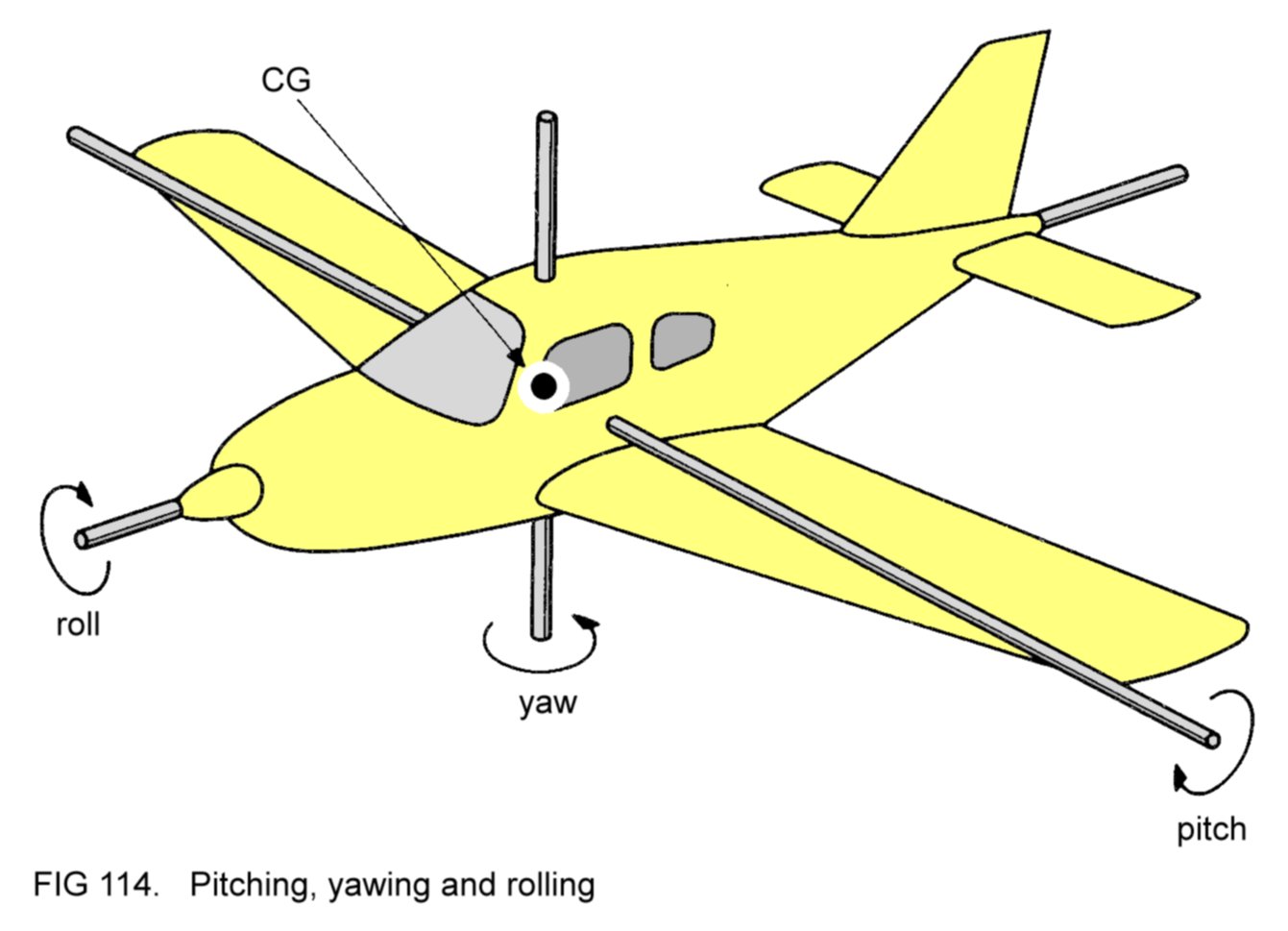
The aircraft pitches
about the lateral
axis. The tailplanes enable the aircraft to resist pitch disturbances -
they confer what is termed
longitudinal
stability.
The aircraft yaws about
the vertical
axis. The fin enables the aircraft to resist yaw disturbances - it
confers what is termed directional
stability.
The aircraft
rolls about the longitudinal
axis. The wings are arranged in such a
manner than they enable the aircraft to resist roll disturbances - the
arrangement confers what is termed lateral
stability.
3.8 STABILITY
3.8.1
Longitudinal
stability
Remember
that the tailplanes generate the tail down-force, and that this force,
because of the manner in which it is generated, responds to the same
factors which affect the lift force generated by the wings.
Suppose
that while an aircraft is in level flight, a gust of air disturbs it,
causing the nose to pitch upwards. The aircraft will now start to
climb, decelerating as it does so (in the same manner as a car tends to
slow down as it runs up a hill).
The reduced speed will
decrease the tail
down-force. From consultation of Figure 2,
we can see that
in this situation the lift force, acting behind the CG as it does,
will now raise the tail, so restoring the aircraft to level flight.
Thus
although the gust upsets the aircraft, the stability conferred by the
tail planes will soon restore it to its original flight path.
If a gust pitches the
nose downwards, the aircraft will
start to descend, accelerating as it does so. The faster speed will
increase the tail down-force and the tailplanes will be pulled down,
again bringing the aircraft back to level flight.
3.8.2
Directional
stability
Figure 115 shows the
view from above of an aircraft which has just
been
disturbed by a gust of air causing the nose to yaw to the left. The
aircraft, because of its inertia,
will tend to continue in its
original direction of motion. The result is that the airflow is as
shown in the diagram.

It can be seen that the
fin, which
is now at a shallow angle of attack to the airflow, will generate a
force in the same manner as the wing generates lift, and that this
force will have the effect of swinging the tail to the left, restoring
the aircraft to its original flight path.
Of course, the fin will
exert an opposite restoring force if a gust
causes the nose to yaw to the right.
The aircraft designer
can maximise the restoring effect of the fin by
one of two means, or a combination of both:
(a) by increasing the
area of the fin;
(b) by making the
fuselage longer and thereby increasing the distance
between the fin and the CG.
It is usual for the
designer to limit the directional stability of his
aircraft, for reasons which will be explained later.
3.8.3
Lateral stability
On
most aircraft, lateral stability is conferred by canting the wings
slightly upwards from root to tip. This arrangement is
termed dihedral
(Figure 116).

Now, imagine that this
aircraft has been
disturbed by a gust of air which has caused it to roll to the left.
The effect is to adjust the disposition of the lift force, which is now
tilted to the left) relative to the weight force (which, of course,
still acts vertically downwards), as shown in Figure 117.

The
effect is that these two forces between them produce a sideways-acting
force (F) as shown. This force tends to pull the aircraft to the
side, with the result that the airflow now strikes the left-hand side
of the aircraft more than the right-hand side. This tendency of the
aircraft to move to the side is termed sideslip (to the left in this
case), and one consequence of the effect of the airflow is that the
left wing has now a greater angle of attack than the right wing,
because of its dihedral. (This can be more easily appreciated if a very
marked wing dihedral is imagined.) So - the left wing generates more
lift, which tends to level the aircraft, restoring it to its
undisplaced state.
Of course, the dihedral
will also help to level the aircraft after a
gust has caused it to roll to the right.
High-winged aircraft
tend to be laterally stable by their very design.
Figure 118
shows such a machine in a sideslip to the right.

The airflow,
striking the aircraft more on the right-hand side, exerts a drag
effect on the wing, as shown in Figure 118, which induces the aircraft
to roll to the left, restoring it to its original flight path. Because
of this natural lateral stability, high-winged aircraft are usually
designed with less dihedral than low-winged machines.
3.8.4
Interaction of
directional and lateral stabilities
Refer
back to Figure 117, which
shows an aircraft in a sideslip to the left.
Figure 119 represents the view from above, showing the airflow pattern
at the fin.

Of course, in
Figure 119 the fin will cause the tail to swing to the right, thus
restoring the symmetrical airflow pattern past the aircraft.
Effectively, the
slideslip motion of the aircraft has been cancelled
by the action of the fin.
When this occurs, the
differential
angle of attack effect imparted by the wing dihedral is nullified -
there will be no tendency for the lower wing to level itself.
Furthermore, while the tail is swinging to the right, the aircraft's
right wing is travelling slightly faster through the air than the left.
The result is that the right wing generates more lift, aggravating the
situation. In other words, the aircraft is laterally unstable - a
lowered wing starts off a sequence of events which finally causes it to
drop still further.
Now the dilemma of the
designer can be
appreciated. If the directional stability is too strong, the aircraft
will be laterally unstable, even though its wings may Incorporate
dihedral. On the other hand, too little directional stability, although
allowing the dihedral to carry out its function effectively, will
permit the nose of the aircraft to yaw from side to side in gusty
conditions, with consequent discomfort to the occupants of the machine.
In
practice, a compromise solution is adopted, in which the aircraft is
designed to have good directional stability without being too laterally
unstable.
3.8.5 Effect
of position
of centre of gravity on stability
For
this discussion, it will be imagined that a heavy box is to be stowed
in the cabin of a typical light aircraft. If the box is loaded at the
forward end of the cabin, the effect is to move the CG of the loaded
aircraft further forward. Conversely, stowage of the box at the rear
end of the cabin has the effect of moving the CG rearward.
These
situations are shown in Figure 120.

3.8.5.1
Effect on
longitudinal stability
The
tail down-force has the stabilising effect of bringing the nose of the
aircraft back to its original position after disturbance. Refer back
to Figure
2, which
showed the usual disposition of the
weight force, the lift force and the tail down-force during flight. It
is possible for the pilot to vary the magnitude of the tail down-force,
using the aircraft's controls.
Now, suppose that the
aircraft
is loaded so that its CG is further rearward, coinciding with the point
from which the lift force acts, as in Figure 121. In this case, the
original tail down-force would now pull the tail down, thus pitching
the nose up.

To prevent this, the
pilot would have to use
his controls to reduce the tail down-force to zero, thus restoring the
equilibrium. But now, if a gust upsets the aircraft, the tailplanes
will have no stabilising effect, because, regardless of the aircraft's
speed, the tail down-force would remain zero.
Taking the
argument a stage further, suppose now that the CG was so far to the
rear that it was behind the point from which the lift force acts, as in
the top image in Figure 122.

It can be seen that the
lift force, because it
is now acting ahead of the CG, will have the effect of pitching the
nose up, and to prevent this from happening, the pilot would have to
adjust his controls so that the tail force acted upwards, as in the
lower image in Figure 122.
Well,
the equilibrium has been restored again, but imagine that a gust now
pitches the nose down. The aircraft will, of course, start to
accelerate - the tail force will increase, pulling the tail further up,
and the situation would quickly develop into a steep dive. In other
words, the aircraft is longitudinally unstable. (The
reader is left to
prove that this instability would aggravate any pitch up of the nose
caused by a gust.)
The conclusion can be
drawn that, as the CG
of an aircraft is positioned further rearwards, so its
longitudinal
stability decreases,
and, at extreme rear CG positions, the aircraft
may become longitudinally unstable. Conversely, forward CG
positions
enhance
longitudinal stability. (However, extreme forward positions of
CG have a detrimental effect on aircraft controllability, for reasons
which will be explained later.)
Now it can be understood
why the
manufacturer specifies limits for the CG positions in his aircraft. A
CG position outside these limits renders the machine unsafe for flight.
The importance of correct loading can be appreciated, and one of the
pilot's responsibilities is to ensure that this requirement is complied
with.
3.8.5.2
Effect on
directional stability
In 3.8.2 it
was mentioned that the stabilising effect of the fin was enhanced when
it was positioned further from the CG. Using this argument, it is plain
that rearward
CG positions reduce the distance between the CG and the
fin, with a consequent reduction
in directional stability. Conversely,
forward CG
positions enhance
directional stability.
3.8.5.3
Effect on lateral
stability
Because
of the interaction described earlier, rearward CG positions, decreasing
the directional stability, have the effect of improving the lateral
stability, and vice versa. The effect is too small to be of consequence.
3.9
AIR DENSITY
The
effects of varying air density on the aerodynamic forces involved in
flight have already been mentioned. Now, remembering that the earth's
atmosphere becomes less dense with increasing height, the practical
results of this phenomenon will be discussed.
As a preamble, the
reader is recommended to consult 2.6.4.2
so that he may be familiar
with the effect of varying air density on the relationship between IAS
and TAS.
Now, suppose that an
aircraft is cruising at sea level
at 100 knots IAS, with its wings at the most efficient angle of attack.
Of course, at sea level, assuming ISA temperature conditions, the
aircraft's TAS will also be 100 knots.
However, at an altitude
of, say, 5000 feet, it will be appreciated that TAS will be greater
than IAS. So, if the aircraft is to cruise at 5000 feet with its wings
at their most efficient angle of attack, will 100 knots IAS be the
correct speed to fly at (giving a TAS greater than 100 knots), or
should a lower IAS be aimed for (to give a TAS of 100 knots)?
To
determine the answer, remember that the most efficient angle of attack
at 5000 feet will be exactly the same as at sea level (as explained in
3.6).
Now, as has been stated, a
wing in less dense air generates less
lift than in more dense air, assuming that its angle of attack and
speed through the air remain constant. Of course, the 'speed through
the air' is exactly equivalent to TAS.
So, let us suppose that
an IAS is chosen which gives a TAS of 100 knots. But at 5000 feet, the
wings set to their most efficient angle of attack will be moving
through less dense air and so they will generate less lift than at sea
level - the aircraft will therefore be unable to maintain level
flight. It would be possible to restore the lift by one of two means:
(a) increase the angle
of attack at this speed of 100 knots TAS - but
then the wings are less efficient!
(b) increase the TAS
until the most efficient angle of attack generates
the required lift.
Obviously,
(b) is the solution, the aircraft must be flown at a greater TAS. How
much greater? Perhaps the reader will have guessed the answer - 100
knots IAS will give exactly the correct TAS for the most efficient
angle of attack.
But what about drag?
Will the total drag be
greater at this higher TAS? No, because the air is less dense than at
sea level. In fact, both the lift force and the drag force generated by
this particular aircraft, flying at 100 knots IAS with its wings at
this particular angle of attack, will always have the same respective
values, regardless of height.
Although we have
considered only
the case of cruising at the most efficient angle of attack, it can be
shown that the general aerodynamic characteristics of an aircraft are
the same at any particular IAS, regardless of height, and this
theoretical conclusion is, indeed, borne out in practice. Thus the
limiting speeds referred to in 2.6.4
are in terms of IAS rather than
TAS.
3.10
THRUST: THE PROPELLER
Thrust is necessary to
oppose drag, so that an aircraft may maintain sustained flight. Thrust
is generated by the propeller, which is rotated by the engine. The
propeller produces thrust by the same aerodynamic action by which the
wing produces lift, and the aerofoil shape of a propeller blade closely
resembles that of a wing. For good propeller efficiency, therefore, the
blade should meet the airflow at the most efficient angle of attack,
which is about 4° for most designs.
The discussion which
follows
concerns propellers whose blades are attached to the propeller hub at
a fixed angle. This angle, called the blade angle, is
related to an
aerodynamic property of the propeller, termed pitch. Accordingly,
our
discussion will concern fixed-pitch
propellers.
In flight, the direction
of the airflow which passes the propeller
blades is governed by:
(a) the forward motion
of the aircraft;
(b) the rotational
motion of the propeller.
Consider a point on one
of the blades. Its direction of motion through
the air can be determined by reference to Figure 123.

Of course, the airflow
direction at the point considered will be in
exactly the opposite direction, as shown. So, it is merely necessary to
arrange that the blade at that point meets the airflow at the most
efficient angle of attack, as in Figure 124.
Note that the blade
angle is the angle between the blade chord line and
the direction of rotation.
Figure 124 shows the
total reaction generated by the blade. In order to
appreciate how the thrust is derived, the total reaction can be
resolved, not into lift and drag, but into a forward-acting force (T)
and a force (Q) acting in the opposite direction to the rotation, as in
Figure 125.
Of course, T is the
thrust. The force Q is called torque and it
opposes the rotation of the propeller. The propulsive force developed
by the engine is necessary to oppose the torque and thereby keep the
propeller turning so that it may continue to generate thrust.
But now a problem arises
- the tips of the blades are moving much
faster in the direction of rotation than the roots (Figure 126).
And so the direction of
airflow will differ at each location, as shown
in Figure 127.
A means must be found to
ensure that, at any point on the blade, it is
inclined to the airflow at its most efficient angle of attack. This is
achieved by designing the blades to incorporate a helical twist so
that the blade angle is greatest at the root, and decreases towards the
tip, as represented in Figure 128.
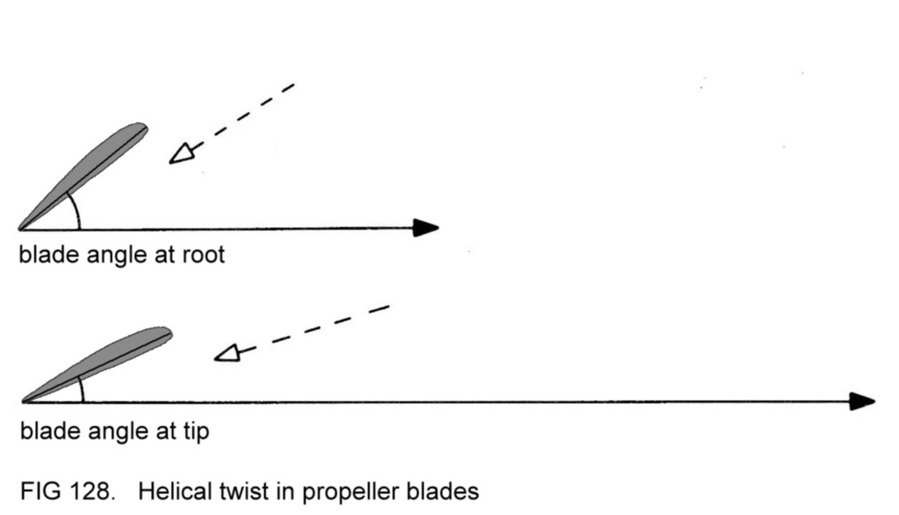
3.10.1
Effect of varying
engine power output
Let it be assumed that
the argument in 3.10 referred to a propeller
driven by an engine set to cruising power. Now, suppose that the
throttle is opened, to increase power. The sequence of events is that,
firstly, the increased engine propulsive force exceeds the opposing
torque and therefore makes the propeller rotate more quickly. In other
words, there is an increase
in RPM.
This has the effect of
increasing the both the speed of airflow past
the blades and
their angle of attack, as
shown in Figure 129. The result is that the propeller generates
more
thrust. Of
course, it also generates more torque, which is
exactly balanced by the increased engine propulsive
force. The reader is left to determine the effect of closing the
throttle from cruising power.

3.10.2
Effect of speed on
RPM
Consider a point on one
of the propeller blades when the engine is set
to cruising power and the aircraft is flying at cruising speed at
constant height (as was shown in Figure
124). Now
suppose that
the
pilot uses his controls to make the aircraft's nose pitch down. This
will cause the machine to descend, and it will therefore start to
accelerate.
Reference to Figure 130
shows that the increased forward
speed effectively reduces
the angle of attack of the blades.
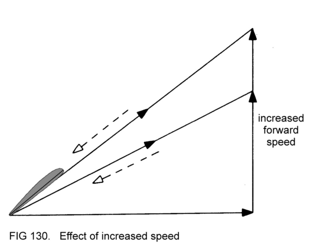
The result is that the
total reaction is reduced in magnitude, and,
accordingly, both the thrust and
the torque.
The propulsive force from
the engine, exceeding this reduced torque, will make the RPM increase.
The effect of increased
RPM, as previously noted, is
to increase the blade speed and angle of
attack, with consequent increase in thrust and torque.
Equilibrium is re-established when the torque again matches the engine
propulsive force. The engine will then have stabilised
at higher RPM.
The reader is left to
prove that, if the aircraft's nose is made to
pitch up to make the machine fly more slowly, then the RPM will
decrease.
Note that here it is
purely the effect of varying speed which
causes
the RPM to change, and that this occurs even though the throttle
setting is unaltered.
From the foregoing
remarks, it may be appreciated that if the aircraft
is flying at high speed with the throttle set for high power, it is
possible that the RPM will exceed the limit imposed by the
manufacturer. This overspeeding
of the engine may subject it to forces
it is not designed to withstand and can be prevented by judicious
handling of the engine controls.
3.10.3
Windmilling
Suppose that while the
aircraft was cruising, the pilot fully closed
the throttle, thereby reducing the RPM to idling power. With the
consequent large reduction in thrust, the aircraft's drag would make
it decelerate. But suppose now that the pilot pitched the nose down so
that speed was maintained by the assistance of gravity. The situation
would be as shown in Figure 131.

It can be seen that the
blade now meets the airflow at such an angle of
attack that the total reaction acts in a completely different direction
from before, as the diagram shows. Let us now resolve this total
reaction
into components (Figure 132).

The result is
remarkable. Two conclusions can be drawn.
Firstly, the thrust is
acting backwards,
as drag. In other words, the
propeller is attempting to slow down the aircraft. It can be
appreciated that a force is necessary to oppose this drag and that of
the rest of the aircraft, in order for speed to be maintained. In fact
it is purely the effect of gravity, acting on the descending aircraft,
which is providing the force to counter these drag effects.
Secondly, the torque is
acting in the same direction as the rotation of
the propeller - it is assisting the rotation rather than opposing it.
Even with the engine delivering no power, the propeller will keep
turning, driven by the airflow passing it. This windmilling of the
propeller is a reversal of the normal situation - now it is turning the
engine.
3.10.4
Propeller
efficiency
A measure of propeller
efficiency is the ratio of thrust generated to
torque generated under any particular conditions. It has been said
already that angles of attack for the propeller blades of about 4° were
most efficient because of the aerodynamic similarity between the blades
and the aircraft's wings, and this is so even though the total
reaction is being resolved into thrust and torque rather than into lift
and drag.
3.10.4.1
Effect of speed
on propeller efficiency
Consider an aircraft
making its take-off run. At the low forward speed
and with the engine set to maximum power, the situation at the
propeller is as shown in the top image in Figure 133.

Notice that, because of
the aircraft's low forward speed, the
propeller blades meet the airflow at a high angle of attack and so the
propeller efficiency is lower than optimum - the ratio of thrust to
torque is poor. This is a severe penalty and a waste of engine power at
a time when the highest possible thrust is required to confer good
acceleration to the aircraft so that it quickly becomes airborne.
During cruising flight,
the propeller performs much better - with the
higher forward speed of the aircraft and the engine set to cruising
power, the blade will at or or near its most efficient angle of
attack.
The situation during
take-off would be improved if the blade angle were
lower, to match the low forward speed of the aircraft, as represented
in the lower image in Figure133.
The reduced angle of
attack results in the propeller developing
slightly less thrust, but considerably less torque. In the situation
shown in the top image in Figure 133 the engine RPM were
reduced by the
retarding
effect of the high torque. Now, with the lower blade angle, the engine
will be able to attain higher RPM, with the result that the speed of
motion of the propeller blades through the air will be greater.
Accordingly, the thrust will now be greater, this effect more than
offsetting the reduced angle of attack effect as would be expected with
the blades working more efficiently.
But will this propeller
with lower blade angle perform satisfactorily
in cruising flight, when the aircraft's forward speed is higher?
Figure 134 shows that the blade is now at a lower angle of attack than
optimum, and so its efficiency is poor.
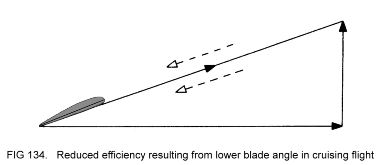
It seems that a
fixed-pitch propeller will be efficient either at low
speed, or at higher speed, depending on its blade angle, but not both.
Most small aircraft, whose acceleration during take-off is not so
critical, are equipped with fixed-pitch propellers designed
for
optimum efficiency in cruising flight.
Later
on we shall look at propellers in which the blade angle can be varied
by the pilot according to the phase of flight. These variable-pitch
propellers
confer efficiency at all aircraft speeds.
4 AIRCRAFT HANDLING
Every flight involves a
certain amount of preparation beforehand so
that, once the flight has begun, the pilot is able to operate his
aircraft safely and efficiently. Not surprisingly, the depth of
pre-flight planning is related to the complexity of the intended flight
- a long cross-country operation will involve more detailed planning
than a brief flight in the vicinity of the base airfield.
In this Section, we
shall be concerned with the manner in which the
controls are used to make the aircraft behave as required during the
various phases of flight. It is emphasised that aircraft handling is
merely one aspect of the whole concept of flight management.
Throughout any flight
the aircraft should be operated in accordance
with its checklist. The observations below are of a general nature,
applicable to most light aircraft. Initially, we shall be concerned
with machines having fixed-pitch propellers and fixed landing gear.
4.1
AIRFRAME LIMITATIONS
The reader will recall
that certain limitations are applied to the
airframe.
Firstly, the pilot must
ensure that before flight the aircraft is
loaded in compliance with the loading
limitations
set down in the
Flight Manual.
Secondly, during flight,
he must observe the various speed
limitations.
Besides the limitations discussed in 2.6.4
(flap limiting speed, Vno
and Vne), the Flight Manual will specify the maximum
speed permitted
for flight in turbulent air (to protect the airframe from
overstressing) and the maximum
crosswind component
acceptable for
take-off and landing. This limitation is primarily to prevent the
control difficulties which would arise from operation in stronger
crosswinds.
4.2 ENGINE
HANDLING AND
OPERATING LIMITATIONS
4.2.1
Control of power
To
increase engine power output the throttle is opened (by pushing the
lever forwards) to attain higher RPM. Maximum power, or 'full power',
implies throttle fully opened, or until the maximum permitted RPM are
reached, whichever is the more restrictive. (Remember that for any
particular throttle setting, RPM increase with the aircraft's speed.
With many designs, the throttle may be opened fully at low speeds, but
will require closing partially at higher speeds to prevent violation of
the maximum RPM limitation.)
Minimum power (idling
RPM) is delivered when the throttle is closed
(lever fully rearwards).
Of course, increased
power results in increased thrust from the
propeller, and vice versa.
4.2.2 Use of
mixture
control
As
explained in 2.2.6 the mixture
control is used to lean out the mixture
for cruising flight. The usual procedure is as follows:
(a) set the mixture
control to 'rich' (if not already so);
(b) set chosen RPM with
the throttle lever;
(c) move the mixture
control lever backwards until the RPM start to
decrease;
(d) move the mixture
control lever forwards sufficiently to regain the
original RPM setting.
The
mixture strength is now correct for
the chosen RPM setting and cruising
altitude. A
change in either of these factors will
necessitate
re-adjustment of the mixture control.
4.2.3 Engine
operating
limitations
The
pilot must observe the engine operating limitations stated in the
Flight Manual. The maximum permitted RPM will be specified, as will the
restrictions on the use of the mixture control. These latter are often
expressed in terms of the power setting above which, and the altitude
below which, the control must be set to rich.
Periodically, the
pilot should check that the oil temperature, oil pressure and fuel
pressure gauge readings are within the limits specified in the Flight
Manual.
Excessive oil
temperature might occur in warm weather if
the engine is operating for long periods at high power. Setting
reduced power should rectify the situation.
An abnormally high
oil temperature indication accompanied by abnormally low oil pressure
signifies malfunction of the oil system and these may be the first
symptoms of impending engine failure. If such indications are observed
the flight should therefore be terminated as soon as possible and the
fault investigated.
Abnormally low fuel
pressure signifies
malfunction in the fuel system. If the engine-driven pump is at fault,
pressure might be restored by switching on the electrically-driven
pump. If this remedy has no effect, it is possible that a leak has
occurred in the fuel pipeline. In either case the flight should be
terminated as quickly as possible, particularly if a suspected leak has
occurred, since this is a potential fire hazard.
4.3 PICKETING
AND USE OF
CHOCKS
When circumstances
require, a parked aircraft should be tied down, or picketed, and its
wheels chocked.
Incorporated in
the lower surface of each wing is a reinforced
anchor
(or picketing)
point.
Picketing
involves connecting these to similar anchor points embedded in
the ground, using suitable tie-down
straps.
This precaution will prevent any tendency for the
machine to be overturned by strong winds. The straps should be
neither too loose (which would allow a strong wind to lift the machine)
nor too taut (to avoid straining the airframe structure). Figure 135
demonstrates.

The aircraft should be
picketed whenever strong winds are blowing or
if they are forecast to occur.
Chocks
are blocks of metal or wood which are positioned in front of and behind
each mainwheel. They prevent movement of the aircraft if the parking
brake system fails (Figure 136).

Common sense dictates
that whenever the aircraft is to be parked
outside for a considerable period of time:
(a) it is picketed;
(b) the wheels are
chocked;
(c) the control lock(s)
are employed.
4.4
MANHANDLING AND
POSITIONING THE AIRCRAFT FOR ENGINE-STARTING
If not already parked
so, the aircraft should be manhandled into a
suitable position for engine-starting.
Aircraft manhandling
requires special care because the airframe
structure is
relatively delicate. Whilst being strong enough to bear the aerodynamic
loads experienced during flight, the structure might easily be damaged
by careless handling on the ground.
It is usual for each
aircraft to be equipped with a tow
bar which
can be connected to the nosewheel landing gear
unit, enabling the machine to be pushed, pulled
or steered by hand for positioning. When this is the case, no part of
the airframe structure should be pushed or pulled. If no tow bar is
provided the machine should be manhandled in accordance with the
manufacturer's instructions. Vulnerable areas, such as the flight
controls, should never be pushed.
When the aircraft is in
the
required position the brakes should be applied with the park brake
control
and the tow bar disconnected and stowed. The machine should be
positioned such that there are no buildings or other aircraft
immediately behind the tail. This is because, whenever the engine is
running, the propeller sends back a swirl of air - the 'propwash'. Any
loose stones on the ground in the vicinity of the aircraft might be
flung backwards by the propwash - the precaution mentioned above will
ensure that such flying debris will not cause damage. Under no
circumstances should the engine be started while the aircraft is
inside a hangar.
4.5
PROPELLER HANDLING
Any person who
comes into contact with a rotating propeller risks lethal injury. A
propeller at rest should never be turned by hand unless absolutely
unavoidable (for manhandling the aircraft clear of others in confined
hangarage or for close inspection of the individual blades).
If the propeller must be
turned for these or any other reasons, the
following precautions should be taken:
(a) apply the brakes
with the park brake control;
(b) ensure that both
magnetos are switched off;
(c) assume that the
propeller is 'live'. If the magneto control is
faulty it is possible that turning the propeller might start the
engine. By ensuring that one's body is kept clear of the propeller arc
(Figure 137) injury will be prevented should this unlikely occurrence
happen.

(A
few designs of aircraft have no electric engine starter. Their engines
are started by turning the propeller by hand after the magnetos have
been switched on. This technique requires special training for the
personnel involved.)
4.6
AIRCRAFT INSPECTION
Before
starting the engine, the aircraft and its components should be
inspected for serviceability in accordance with the checklist. The
pilot should check that sufficient fuel and oil are carried for the
intended flight, allowing adequate reserves for contingencies. He
should ensure that:
(a) picketing straps are
removed and stowed or placed well clear of
the aircraft;
(b) the chocks are
removed and stowed or placed well
clear (once the brakes have been applied by the
park brake control);
(c) the control lock(s)
are removed and stowed;
(d) the ground
immediately ahead of the machine's nose is clear of
obstructions.
4.7 ENGINE
STARTING
Once
the pilot has entered the cabin he should close and latch the doors,
adjust and lock his seat in position and fasten his harness. Internal
serviceability checks should be actioned as detailed in the checklist.
Just
prior to starting, the pilot should check visually that no personnel
are in the vicinity outside the aircraft, especially near the
propeller or behind the tail.
The starting procedure
should be
carried out in compliance with the checklist. Once the engine is
running, check that the oil pressure is satisfactory. (If it is not,
stop the engine again - it is obviously unserviceable; the aircraft
should be grounded until the fault has been rectified by qualified
engineers.) Adjust the throttle lever to achieve the recommended RPM
for warming up.
Verify the correct
function of each magneto by
switching the key from BOTH to R and back to BOTH, and then to L and
back to BOTH. With the key at R or L the RPM should have decreased
slightly (since combustion in the cylinders is less efficient) and
should have re-attained the warm-up setting when the key has been
switched back to BOTH. If the engine stops when the key is at R or L
then that magneto is evidently faulty. If no RPM drop is observed then
the magneto control switch is faulty. In either case the engine is
unserviceable.
After starting, electric
services such as the
radio and the anti-collision lights can be switched on if desired, and
the DI synchronised with the magnetic compass.
4.8 TAXYING
'Taxying' is the word
used to describe ground manoeuvring of the
aircraft under the thrust from the propeller.
Before
moving away from the parking position the pilot should first check that
the vicinity of the aircraft is clear of obstructions. He should then
close the throttle and release the park brake control. A gentle
increase in power will now get the machine moving forward.
As
soon as the aircraft starts to move the throttle should be closed and
the toe brakes applied to check their operation. After releasing the
brakes again the throttle can be used as before to start the machine
moving forward.
Although modern aircraft
are not difficult to
manoeuvre on the ground, they are not as easily controlled as cars. For
this reason they should not be taxied at high speed. A general rule
when manoeuvring near buildings or other aircraft or on poor ground
is not to taxi faster than a brisk walking pace.
Once the
throttle has been used to start the machine moving forward, it should
be partially closed again so that the engine delivers just enough power
to maintain taxying speed. To slow down, the throttle should be closed.
It is noteworthy that the propeller generates a certain amount of
thrust even when
the
throttle is fully closed. Therefore to slow down
further, or to stop, the brakes must be applied.
To turn the
machine to the left or right the rudder pedals are moved as
appropriate to activate the nosewheel steering mechanism. Tighter
turns may be made by differential use of the brakes. (For example,
pushing forward the left pedal will steer the aircraft to the left.
Applying the left toe brake will tighten the turn.)
When
taxying, the control wheel should normally be held in the central
position. On some types of aircraft it is recommended that certain
control wheel inputs should be made when taxying in conditions of
strong wind in order to assist with control. The Flight Manual will
specify the inputs to be made.
At all times the pilot
should
look out for the presence of obstructions or poor ground so that
avoiding action can be taken in good time.
The following flight
instrument checks should be made when convenient
during a turn to the left and one to the right:
(a) the TBI indicates
appropriate turns;
(b) the DI heading
indications decrease when turning left and increase
when turning right;
(c) the magnetic compass
heading indications behave as in (b);
(d) the AI continues to
show a level attitude with the wings level.
Whenever
the engine is running, a little oil escapes past the pistons into the
cylinders. At power settings well above idling RPM (throttle closed)
this oil is burnt along with the fuel-air mixture. At lower power
settings, however, some of the oil forms a film over the spark plug
electrodes, inhibiting spark occurrence, possibly to the extent that
the engine runs roughly and fails to deliver the power that it should
when the throttle is opened again. To guard against this possibility,
the throttle should be set to warm-up RPM whenever the aircraft is
brought to a halt for more than a few seconds. This precaution should
ensure that all escaping oil is burnt and the spark plug electrodes
are therefore kept dry.
4.8.1
Brake failure
In the event
of failure of the brakes the engine should be stopped immediately
(unless its use will definitely assist the pilot in dealing with the
situation) and the aircraft steered away from obstructions while it
decelerates. It is worth remembering that grass will slow down the
machine more quickly than hard ground. Steering onto grass (if
practicable) will thus help to bring the aircraft to a halt.
4.9
ENGINE TESTING
With
most designs of engine the manufacturer will recommend a testing
procedure to be carried out before take-off as detailed in the
checklist.
Since the test involves
the use of a high power setting, the following
precautions should first be taken:
(a)
the aircraft should be halted on firm, non-slippery debris-free ground
and the brakes applied firmly with the park brake control;
(b) the
machine should be positioned, when practicable, facing nose into the
wind. This will assist engine cooling and will help to prevent forward
movement of the aircraft;
(c) the vicinity of the
machine, especially behind the tail, should be
checked as being clear of personnel and other aircraft;
(d) the oil temperature,
oil pressure and fuel pressure should be
verified as being within the specified limits.
Primarily,
the purpose of the test is to check the efficiency of the ignition
system, although other engine controls also require exercising.
Typically, the engine test might proceed as follows:
(a) open
the throttle to achieve a specified RPM indication (checking that the
brakes are preventing the aircraft from moving forwards - if not, the
throttle should be closed again and the brakes re-applied);
(b)
switch off each magneto individually as described in 4.7.
With the key
at R or L the RPM will have decreased slightly from the original
setting. In each case the RPM drop should not exceed the allowed
maximum and the engine should continue to run smoothly. When the key is
switched back to BOTH, the RPM should increase again to the original
setting. If the RPM drop at R or L is more than the permitted maximum,
or if the engine runs roughly, the cause might be oil on the spark
plug electrodes, in which case the problem can usually be cured by
running the engine (with the key at BOTH) at the test RPM setting for a
minute or so to burn away the oil (making sure that the various gauge
indications remain within the specified limits) and then repeating the
ignition test. If the result is still unsatisfactory the engine must
be considered unserviceable for flight. (Ensure that the key is set to
BOTH after completion of the test);
(c) select carburettor
heat
'on'. If the control is functioning correctly, the RPM will decrease
slightly from the original setting (since with hot air entering the
carburettor, the engine delivers less power). Select the control back
to 'off' and verify that the RPM increase again to the original
setting.
If no RPM drop is observed when the control is 'on', or if the RPM fail
to increase again after reselection to 'off', the engine is
unserviceable. Besides testing for serviceability, the procedure just
described will remove any ice which might have built up in the
carburettor whilst taxying;
(d) check that the
indications of
the oil temperature, oil pressure, fuel pressure and suction gauges and
the ammeter are within the permitted limits;
(e) close the throttle
and check that the idling RPM and oil and fuel
pressure indications are within the permitted limits;
(f) reset warm-up RPM
with the throttle lever.
If any part of the test
procedure gives unsatisfactory results, the
flight should be abandoned and the aircraft taxied back to the parking
area for the
attention of engineers.
4.10
PRE-TAKE-OFF CHECKS
The
pre-take-off checks are actioned by the pilot (using the checklist) so
that the various controls are correctly set for the take-off and
initial climb. Typically, they include the following:
4.10.1
Airframe
(a) trim wheel(s) set as
recommended;
(b) flaps set as
recommended (check visually that both flaps are at the
selected position);
(c)
check for full availability of unobstructed movement of the control
wheel (and rudder pedals when spring-type nosewheel linkage permits
such movement);
(d) doors closed and
latched;
(e) harness tight;
4.10.2
Engine
(a) throttle friction
tightened to personal preference;
(b) mixture control set
to 'rich';
(c) carburettor heat
control set to 'off;
(d) magneto control key
set to BOTH;
(e) oil temperature, oil
pressure and fuel pressure within the
specified limits;
(f) fuel cock selected
to draw fuel from a tank with sufficient
quantity;
(g) all fuel tank
quantity gauges checked for sufficiency;
(h) electrically-driven
fuel pump switched on;
4.10.3
Instruments
(a) altimeter set to QFE
or QNH;
(b) AI appears erect,
that is, shows a level attitude with the wings
level;
(c) DI synchronised with
magnetic compass;
(d) suction gauge
indication within the specified limits;
4.10.4
Electrical services
(a) anti-collision
lights switched on;
(b) pressure head heater
switched on if weather conditions warrant;
(c) radio (and other
avionics when appropriate) controls correctly set;
(d) ammeter indication
satisfactory.
4.11
PROCEDURE AFTER
LANDING
After
landing, the appropriate actions in the checklist are carried out and
the aircraft is taxied to the parking position. The brakes are applied
with the park brake control. The engine is shut down in accordance with
the recommended procedure. All electric services, including the master
switch, are switched off and the fuel cock is turned off.
If the aircraft is to be
left unattended for a considerable length of
time,
the pilot should carry out the actions described in 4.3
and close and
latch all doors after vacating the machine. If appropriate, covers can
be fitted to protect the aircraft against adverse weather.
4.12 EFFECTS
OF FLIGHT
CONTROLS IN FLIGHT
During
flight, an aircraft's stability helps it to resist pitching
disturbances (nose rising and falling), yawing disturbances (nose
swinging left and right) and rolling disturbances (rising and falling
of one wing or the other). The flight controls are used to overcome
this natural stability when it is desired to change the flight path.
4.12.1
Effect of elevators
Suppose
that while the aircraft is in cruising flight, the pilot moves the
control wheel rearwards. The result will be to displace the elevators
upwards. Effectively, the camber of the tailplane-elevator assembly and
its 'inverted angle of attack' will have been increased, and so the
tail down-force will increase in magnitude (Figure 138).

It
is clear that the tail of the machine will be pulled down by the
increased force, correspondingly pitching
the nose up.
For aerodynamic
reasons (which will be explained later) the aircraft will also lose
speed.
As the machine
decelerates, of course, the speed of the
airflow over the tailplane-elevator assembly will decrease, thus
reducing the magnitude of the tail down-force. Eventually, the nose
will pitch up no further even though the elevators are still
displaced, because the balance of the weight, lift and tail down-forces
will have re-attained equilibrium. The IAS will then have stabilised at
a lower figure.
For the pilot in the
cabin, therefore, the
effect of moving the control wheel rearwards will be to pitch the nose
of the aircraft to a higher
attitude
and to cause a reduced IAS
(Figure 139).

Further rearward
movement of the control wheel will result in an even
higher attitude and another reduction in IAS.
Conversely,
forward movement of the control wheel pitches the
nose down
and will
result in the aircraft eventually stabilising at a lower attitude and
at an increased IAS,
as shown.
4.12.2 Effect
of ailerons
Suppose
that, in cruising flight, the pilot moves the control wheel to the
left. The result will be to displace the left aileron upwards and the
right downwards. Effectively, the camber and angle of attack of the
wing at the left tip are reduced and at the right tip they are
increased (Figure 140).

Accordingly, the lift
generated at the
left wing tip is reduced, and that at the right wing tip is increased.
The lift imbalance will make the aircraft roll to the
left.
Conversely, movement of the control wheel to the right will make the
machine roll to the right. In either case, the rolling
motion will
continue as long as the ailerons are displaced. If the
control wheel is
centralised, the aircraft will remain in whatever bank attitude it
happens to be at. Figure 141 shows the ailerons used to select and
maintain an angle of
bank of 30°
to the left. The view from the pilot's seat is
shown in Figure 142.

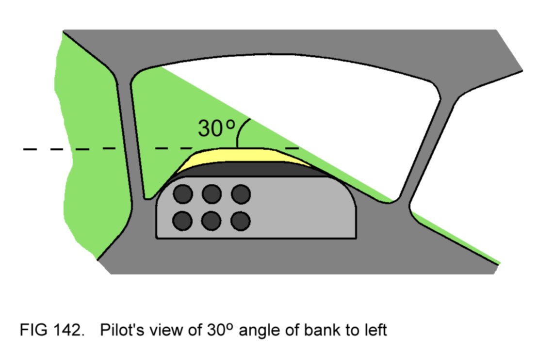
4.12.2.1
Consequence of
bank
Whenever
an aircraft is banked, the sequence of events described in 3.8.4
occurs as a result of the predominance of the machine's directional
stability over its lateral stability. To recap:
(a) the machine
sideslips in the direction of the bank;
(b) its nose yaws
in the same direction under the stabilising influence
of the fin.
The
pilot can visually detect the yaw as a change in the aircraft's
heading relative to a chosen directional
reference point
(such as a
building) at some distance straight ahead of the nose (Figures 143 and
144).


Note
that this yaw is not directly caused by the effect of the ailerons, but
arises as a consequence of bank. By yawing, it will be appreciated that
the aircraft turns;
it will continue to turn as long as the bank is
maintained, with the fin nullifying the sideslip resulting from the
bank.
4.12.3
Effect of rudder
The result of pushing
forward the left rudder pedal is to displace the rudder to the left,
effectively cambering the fin-rudder assembly and inclining it to the
airflow at an angle of attack (Figure 145).

Accordingly, the
assembly will generate a force which will pull it to the right, as
shown. Thus the tail of the aircraft will swing to the right and its
nose will yaw to the
left.
Conversely, pushing
forward the
right pedal will make the nose yaw to the right. In either case, the
yawing motion will continue as long as the rudder is displaced. The
pilot can visually detect the yaw as a change in the aircraft's
heading relative to a chosen directional reference point (Figure 146).
4.12.3.1
Consequence of
yaw
If the aircraft is
yawing under the influence of its rudder, the
airflow
past the fuselage is not symmetrical. In this situation the machine
is said to be skidding
(from the motoring analogy) because even though
it is turning, its path through the air is not in the same direction as
its heading. Figure 147 illustrates.

If the aircraft features
dihedral wing attachment, the asymmetrical airflow will effectively
meet the two wings at different angles of attack. In Figure 147 the
aircraft's right wing will meet the airflow at a greater angle of
attack than the left wing. (This effect is more easily appreciated if
marked wing dihedral is imagined.) The right wing will therefore
generate more lift than the left wing and the machine will start to
roll
to the left.
Similarly, application
of right rudder
(by pushing forward the right pedal) will produce a yawing motion
which will cause the machine to start to roll to the right.
Note
that the roll is caused not directly by the application of rudder, but
occurs as a result of the effect of the asymmetrical airflow on the
physical features of the aircraft designed to impart lateral stability
(wing dihedral or high-winged layout).
4.12.3.2
Propwash-induced
yaw
In cruising flight the
propeller is generating thrust to overcome
the aircraft's drag. As it revolves, the propeller throws back a spiral
propwash. If, as is the case with most designs, the propeller revolves
clockwise (as viewed from the cabin) this spiral airflow will impinge
on the left-hand side of the fin-rudder assembly, as shown in Figure
148.

Of course, the result
will be to make the nose of the machine yaw to
the left.
This
propwash-induced
yaw
can be eradicated by sufficient application of
right rudder, which will enable the fin-rudder assembly to generate a
force opposing the effect of the propwash.
If the propeller
revolves anticlockwise, application of left rudder
will be needed to counteract propwash-induced yaw.
4.13 EFFECT
OF VARYING
PROPWASH STRENGTH
Let
it be assumed that our aircraft is in cruising flight, with sufficient
rudder applied to prevent propwash-induced yaw. Now, suppose that the
pilot increases the engine power. Of course, the strength of the
propwash will increase correspondingly. There will be three
consequences.
Firstly, the speed of
the airflow over the inner
areas of the wings, and hence the downwash flowing past the
tailplane-elevator assembly, will be greater. The assembly will
therefore generate a greater tail down-force even though
the elevator
position is unchanged.
Accordingly, the aircraft's nose
will pitch
upwards. Of course, the pitching motion can be prevented by sufficient
forward movement of the control wheel.
Secondly, the
propwash-induced effect described in 4.12.3.2 will be more marked, and
the aircraft will start to yaw. The motion can be prevented by further
application of rudder as appropriate.
Thirdly, the greater
speed
of airflow over the elevators and rudder will enhance their
effectiveness. In other words, the aircraft will respond more rapidly
to forward and rearward movement of the control wheel and to movement
of the rudder pedals. The ailerons lie outside the propwash and so
their effectiveness is not enhanced.
If the engine power is
reduced the consequences described above will be reversed, as expected.
The rudder applied for counteracting the effect of the propwash in
cruising flight will make the aircraft yaw in the opposite direction
to that caused by the propwash. The yawing motion can be prevented by
reducing the rudder application.
4.14
EFFECT OF VARYING
AIRSPEED ON FLIGHT CONTROLS
Not
surprisingly, the effectiveness of all
the flight controls becomes
enhanced when the aircraft is made to fly at higher IAS, and reduced
at lower IAS.
4.15
EFFECT OF VARYING
CONTROL MOVEMENT
The
greater the movement of the control wheel or rudder pedals, the greater
is the displacement of the associated control and so the aircraft's
response is enhanced.
4.16
EFFECT OF FLIGHT
CONTROLS IN DISPLACED ATTITUDE
It was mentioned in 3.7 that the
motions of pitching, rolling and yawing
occur about three imaginary axes at right angles to each other
intersecting at the aircraft's CG. The reader will appreciate that
this remains the case when the machine is in other than a 'wings level'
attitude. For example, forward and backward movement of
the control wheel when the aircraft is banked will still result in
pitching motion about the lateral axis. Figure 149 illustrates pitching
motion (top image) and yawing motion (bottom image) in banked attitudes
with the view from the cabin.

4.17 FUNCTION
OF FLIGHT
CONTROLS
Having discussed the effect
of the flight controls, we can now consider
their specific functions,
in other words the way they are used to
control the motion of the aircraft.
4.17.1
Function of
elevators
We have seen that the
elevators can be used to make the aircraft adopt
and maintain any desired pitch attitude. In practice, the attitude is
chosen to achieve either one of two purposes, depending on the phase of
flight. They are:
(a) to control the
vertical flight path of the aircraft;
(b) to control the IAS.
4.17.2
Function of
ailerons
The ailerons are used to
select and hold any chosen angle of bank when
it is desired to make the aircraft turn and to remove bank when
straight flight is desired. Remember that the turning
effect results as a consequence of the directional stability imparted
by the fin.
4.17.3
Balance: function
of rudder
The reader will
appreciate that the fuselage will generate minimum drag
when the airflow past it is symmetrical (viewed from above). The
aircraft's flight is then said to be balanced. Any
asymmetry of
airflow will result in increased total aircraft drag. In this case the
flight is said to be unbalanced.
We have encountered the
two causes of asymmetric airflow, namely
sideslip and skidding, in both of which situations the flight is
therefore unbalanced. Remember that sideslip occurs as the initial
consequence of bank. Skidding results from the yaw arising from
application of rudder or from the effect of propwash on the fin-rudder
assembly.
As we have already seen,
the aircraft's directional stability
automatically cancels any tendency of the machine to sideslip. In the
case of propwash-induced skidding, however, there is no automatic
corrective action. The pilot must prevent the skidding by
counteracting the yawing motion with suitable application of opposing
rudder.
With the wings level,
propwash-induced yaw can be detected as change of
heading. The resultant skidding can therefore be eliminated by choosing
a directional reference point and countering any tendency of the nose
to yaw away from it by appropriate use of the rudder pedals. For
example, yaw to the left can be prevented by pushing the right pedal to
a more forward position, so that the aircraft's nose remains aligned
with the reference point.
If the view ahead is
obscured by mist or haze, or by the engine cowling
in a high attitude, or if it is featureless as during flight over the
sea, some other means must be found to detect the yaw. The balance
indicator will serve this purpose.
The balance indicator
makes use of the fact that whenever the aircraft
yaws, it is turning. Consequently, the ball in the balance indicator is
thrown outwards (in the same manner as the occupants of a car tend to
be flung outwards when it turns a corner). As an example, in the
situation shown in Figure 148
the ball would take up the displaced
position shown in Figure 150.

It can now be
appreciated that displacement of the ball from the
central position is indicative of unbalanced flight. If, in the example
above, the propwash-induced yaw is eradicated by application of right
rudder, the aircraft will cease turning and the ball will revert to
a central position, confirming balanced flight.
The purpose
of the rudder is thus to enable the pilot to maintain
balanced flight
(and hence minimise drag) by preventing
asymmetry of
airflow. Displacement of the balance indicator ball to the right
requires movement of the right rudder pedal to a more forward position
to centralise it, and vice versa.
There are two methods available
to the pilot for turning the aircraft.
He can either apply rudder or select a banked attitude. In the former
method, we have discovered that although the aircraft will turn, the
flight will be unbalanced. For example, suppose that in the example
above the propwash-induced yaw has been corrected as described, and
that the pilot then applies more right rudder. The aircraft will yaw
(and turn) to the right and the balance indicator will be as shown in
the top image in
Figure 151. Evidently, the flight is unbalanced.

If the alternative
method of turning is used, that of adopting a banked
attitude to the right, the ball in the balance indicator will again be
thrown outwards. Because of the bank, however, the ball will lie
centrally in the indicator.
The flight is shown to
be balanced (Figure 151 bottom image), which is
to be expected, since we
know that the airflow past the fuselage is symmetrical in this
situation. Application of bank is obviously a more efficient method of
turning the aircraft.
To summarise: the rudder
is used to balance the flight of the aircraft
in accordance with the disposition of the ball in the balance
indicator. In practice, this technique is used even when there is an
adequate directional reference point ahead of the aircraft, since in
cruising flight the propwash-induced yaw is often not marked enough to
detect visually, whereas the balance indicator ball will show even
slight unbalance. Note that the rudder is not used to turn
the aircraft (except in circumstances which will be discussed later).
4.18 FUNCTION
OF TRIM TABS
We have already seen
that rearward movement of the control wheel will
result in a higher attitude.
Of course, to hold the
aircraft in this higher attitude, the elevators
would have to be retained in the upward-displaced position, against the
restoring effect of the airflow which would attempt to return them to
their undisplaced position.
So far as the pilot is
concerned, he would detect the restoring effect
of the airflow as a pull force needed to hold the control wheel in its
rearward position. It would be desirable if another means could be
found to hold the elevators in the displaced position, and thus relieve
the pilot of the need to maintain the pull force on the control wheel.
The effect is achieved
by rotating the elevator trim wheel backwards
and downwards, which in turn displaces the trim tab downwards. The
airflow, striking the displaced tab, tends to push it, and therefore
the elevators, upwards. Figure 152 shows the airflow following the
contours of the tailplane-elevator-tab assembly after such adjustment
of
the tab position.

Sufficient movement of
the trim wheel will enable the elevators to hold
the aircraft in the desired attitude without the need for the pilot to
apply a pull force on the control wheel. The aircraft is then said to
be trimmed
in the chosen attitude; it will retain this attitude even
if the pilot relinquishes his hold on the control wheel.
Conversely, sufficient
rotation of the trim wheel upwards and forwards
will enable the aircraft to retain any chosen lower attitude set by
forward movement ol the control wheel without the need of a continuous
push force.
In a similar manner, the
rudder trim tab is used to hold the rudder in
the displaced position necessary to counteract propwash-induced yaw and
so maintain balanced flight. If the tab is adjustable in flight, it
can be made to nullify the foot force on the rudder pedals needed to
displace the rudder as appropriate for any chosen power
setting.
When the foot force has been nullified, the aircraft is in trim; it
will fly in balance even if the pilot removes his feet from the
rudder pedals. Rotation of the trim wheel to the right will move the
tab to the left, which in turn will hold the rudder in a
displacement to the right, and vice versa (Figure 153).

If the tab is of the
fixed type, it is usually set for cruising flight.
At power settings other than the cruise setting, the pilot will have
to apply a force on the rudder pedals to hold the appropriate rudder
displacement needed for balanced flight. In other words, the aircraft
will only be in trim in cruising flight.
Although it acts in
precisely the same manner, the function of the
aileron trim tab differs from that of the elevator and rudder tabs.
When the aircraft is constructed, manufacturing imperfections make it
virtually impossible to ensure that the wings are precisely formed and
that each is attached to the fuselage at precisely the same angle of
incidence.
Consequently, it may
well be that during flight the machine
tends to roll gently to the left or right as a result of the ensuing
lift imbalance. Of course, the ailerons can be used to prevent this
tendency, and the need for the pilot to physically hold the
control
wheel in the position necessary to maintain the appropriate aileron
displacement can be obviated by adjustment of the aileron trim tab.
As an example, suppose
that the aircraft tends to roll to the left in
flight, and that the tab is attached to the left aileron. In this case,
the tab should be adjusted upwards,
so that the airflow tends to hold
the left aileron in a downward-displaced
position (and, by virtue of
the control linkage, the right aileron in an upward-displaced
position).
The adjustment is made
by trial-and-error to cancel out the machine's
rolling tendency. Once set, it is unlikely that the tab would need
readjustment unless the aircraft were to be reassembled after
dismantling.
If, in the example just
described, the tab were attached to the right
aileron, it would need to be adjusted downwards to
counteract the
tendency of the aircraft to roll to the left.
4.18.1
Trimming technique
To change the pitch
attitude of the aircraft the control wheel is
moved as appropriate. The pilot should then assess whether a pull
force or a push force is necessary on the control wheel to hold the
aircraft in the chosen attitude. If the former, he should turn the
elevator trim wheel backwards and downwards to nullify the control
wheel force; if the latter, the trim wheel should be turned upwards and
forwards.
If the aircraft has been
trimmed correctly it will retain the chosen
attitude even when the pilot's hold on the control wheel is
relinquished. Any tendency for the attitude to change when the control
wheel is released shows that the machine is not in trim. To rectify the
situation, the control wheel should be used to regain the desired
attitude and then the trim wheel turned as appropriate. Note that the
control wheel, and not the trim wheel, is used to make attitude
corrections.
As already explained,
the rudder is used to balance the flight of the
aircraft. If a push force on the left pedal is needed to centralise
the balance indicator ball, and the rudder features a tab adjustable in
flight, the rudder trim wheel should be rotated to the left to
eliminate the force. Conversely, if a push force on the right pedal is
needed, the wheel should be rotated to the right.
4.18.2
Trim changes
We have seen that two
consequences of increasing power are the
tendencies of the aircraft to pitch up and to yaw, as was described in
4.13. These effects are
called 'trim changes', because the machine will tend to depart from its
original trimmed attitude and to fly out of balance.
The pitching effect is a
change in longitudinal
trim and
the yawing
effect a change in directional
trim. These trim changes can be
counteracted by the pilot by appropriate movement of the control wheel
and rudder pedals. If the control forces are now eliminated with the
trim wheels, the aircraft will again be in trim.
Decreasing power will
result in opposite trim changes. Later on in this
book we shall encounter another cause of longitudinal trim change.
4.19 THE
FLIGHT PATH: THE
THIRD DIMENSION
An aircraft differs from
a surface vehicle in that it is capable of
movement in three dimensions rather than the two available to the
latter
- it can move upwards and downwards. In other words, the aircraft can
be made to climb, descend or fly level as desired by the pilot.
We will now consider the
factors that control the flight path in this
third, vertical, dimension.
Firstly, remember that
there are five forces acting on the machine in
flight. They are: the weight force (W), the lift force (L), the tail
down-force (TDF), the drag force (D) and the thrust force (T). The
magnitude and disposition of these forces will determine whether the
aircraft climbs, descends or maintains level flight, and at what IAS
it does so.
Of the five forces only
W is unchanging (disregarding its decrease as
fuel is consumed). The factors affecting the others are listed below:
(a) L is the dependent
upon the angle of attack of the wings
and
upon the aircraft's IAS;
(b) TDF is dependent
upon elevator displacement and upon IAS. In
reality, TDF has approximately the same magnitude in climbing,
descending and level flight paths, except when the control wheel is
actually being moved from one position to another to change the
aircraft's attitude;
(c) D is dependent upon
angle of attack (because of induced drag) and
upon IAS;
(d) T is directly
related to engine power
setting.
Additionally:
(e) angle of attack is
dependent upon the relationship
between the pitch attitude of the aircraft and its actual flight path.
Examples are illustrated in Figure 154
in which both aircraft have the same attitude. Thus the pitch
attitude
alone is not a direct indication of angle of attack;

(f) IAS depends upon the
magnitude of T and upon the actual flight path
of the aircraft. As an example, a particular power setting will result
in a higher IAS if the machine is made to descend than if it is made to
climb (in the same manner as a car tends to accelerate running downhill
and to slow down running uphill, assuming that the accelerator
pedal position is
unchanged).
Figure 155 shows the
disposition of the five forces in a climb, in
level
flight and in a descent. In each case the IAS is constant, neither
increasing nor decreasing. For simplicity, TDF has been combined with W
and all five forces are shown as acting from one point, which
represents the aircraft. The thick arrows show
the actual flight path of the machine in each situation.
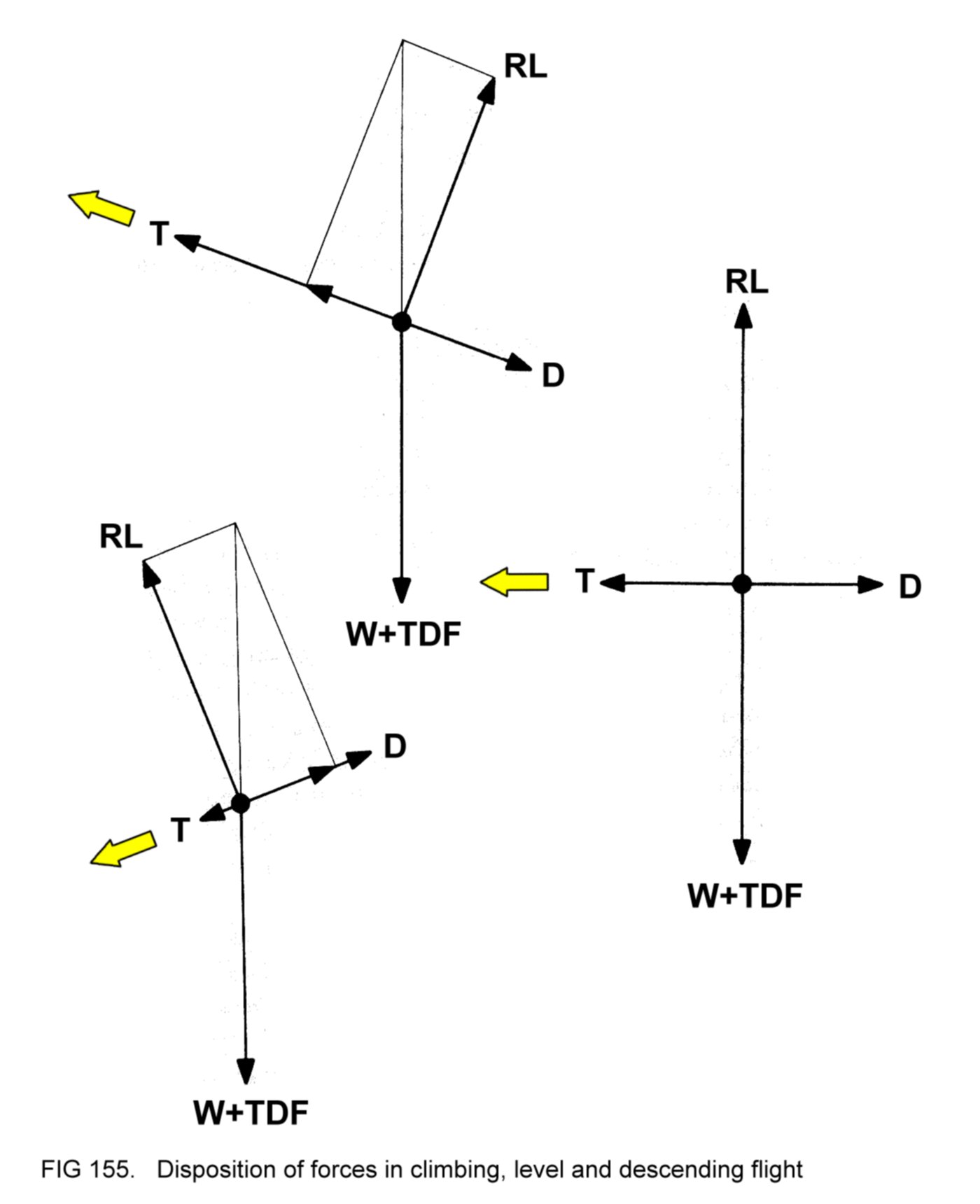
We shall now introduce
the concept of 'required lift', shown as RL in
Figure 155. RL is simply the lift required to maintain the aircraft in
the particular flight path at constant IAS.
Some interesting
observations can be made:
(a) in level flight, (W
+ TDF) is balanced by RL, and D by T. In
magnitude, RL is equal to (W + TDF) and T is equal to D;
(b) in the climb, (W +
TDF) is balanced by RL together with part of T.
D is balanced by the remainder of T. It is clear that in magnitude, RL
is less than (W + TDF), and T is greater than D;
(c) in the descent, (W +
TDF) is balanced by RL together with part of
D. The remainder of D is balanced by T. It can be seen that in
magnitude, RL is less than (W + TDF), and T is less than D.
The correlation between
T and D is as expected - in climbing flight
gravity (in the form of W) is opposing the motion of the aircraft,
whereas in descending flight it is assisting.
Figure 155 also shows
that although RL is less than (W + TDF) during
climbing and descending flight, it is not very much so, especially in
the relatively gentle climbs and descents associated with light
aircraft. In other words, we can take RL as being reasonably constant
regardless of actual flight path.
Bearing this in mind, we
can deduce that since the aircraft in the
bottom image in Figure 154 is
flying with its wings at greater angle of
attack
than the other, it must therefore be at a lower IAS, because RL will be
approximately the same in both cases. We can extend this deduction to
one of considerable practical importance, namely that IAS is the
only
reliable clue the pilot has as to the angle of attack of his aircraft's
wings,
low IAS indicating high angle of attack and high IAS indicating low
angle of attack,
regardless of whether the aircraft is
climbing,
descending or in level flight. Remember that the relationship does not
apply when the flight path is actually changing, only when
the aircraft has stabilised in a steady flight path.
If, as a result of the
pilot resetting his various controls, the actual
lift generated by the wings is greater or less than that required, the
disparity between the two will cause the aircraft to change its flight
path in such a way as to establish a disposition of all five forces in
which the lift generated is again equal to that required.
Of course, the pilot has
no way of assessing the disposition or
magnitude of the various forces. So far as he is concerned, control of
the vertical flight path is achieved by adjustments of the engine power
setting and the pitch attitude of the aircraft. In effect, once the
pilot has chosen a power setting and a pitch attitude the aircraft
will stabilise at a particular IAS in a flight path which disposes the
five forces in equilibrium. Whether
the machine climbs, descends or
flies level will depend upon the actual settings of power and attitude
chosen, as will the IAS at which it stabilises. To make
the aircraft
take up any required flight path and IAS, it is merely necessary for
the
pilot to adopt the power and attitude settings that he knows will
achieve the desired results.
The number of variations
of power and attitude settings is infinite,
within the bounds of the maximum and minimum power available from the
engine and the limit imposed by the wings attaining the stalling angle
of attack. It is evident that the pilot must avoid any combination of
power and attitude that will cause the machine to exceed Vne or the
engine to exceed the maximum permitted RPM.
4.20 STRAIGHT
AND LEVEL
FLIGHT
In straight and level
flight the aircraft maintains a constant heading
(straight flight), a constant height (level flight) and a constant IAS.
4.20.1
Level flight
To achieve level flight,
the aircraft's wings must generate enough
lift to balance exactly the combination of weight and tail down-force.
This required lift can
be generated at low IAS by arranging a high
angle of attack for the wings, or at high IAS by arranging a low angle
of attack. Of course, there are an infinite number of combinations in
between that will give the same result. Figure 156 illustrates.
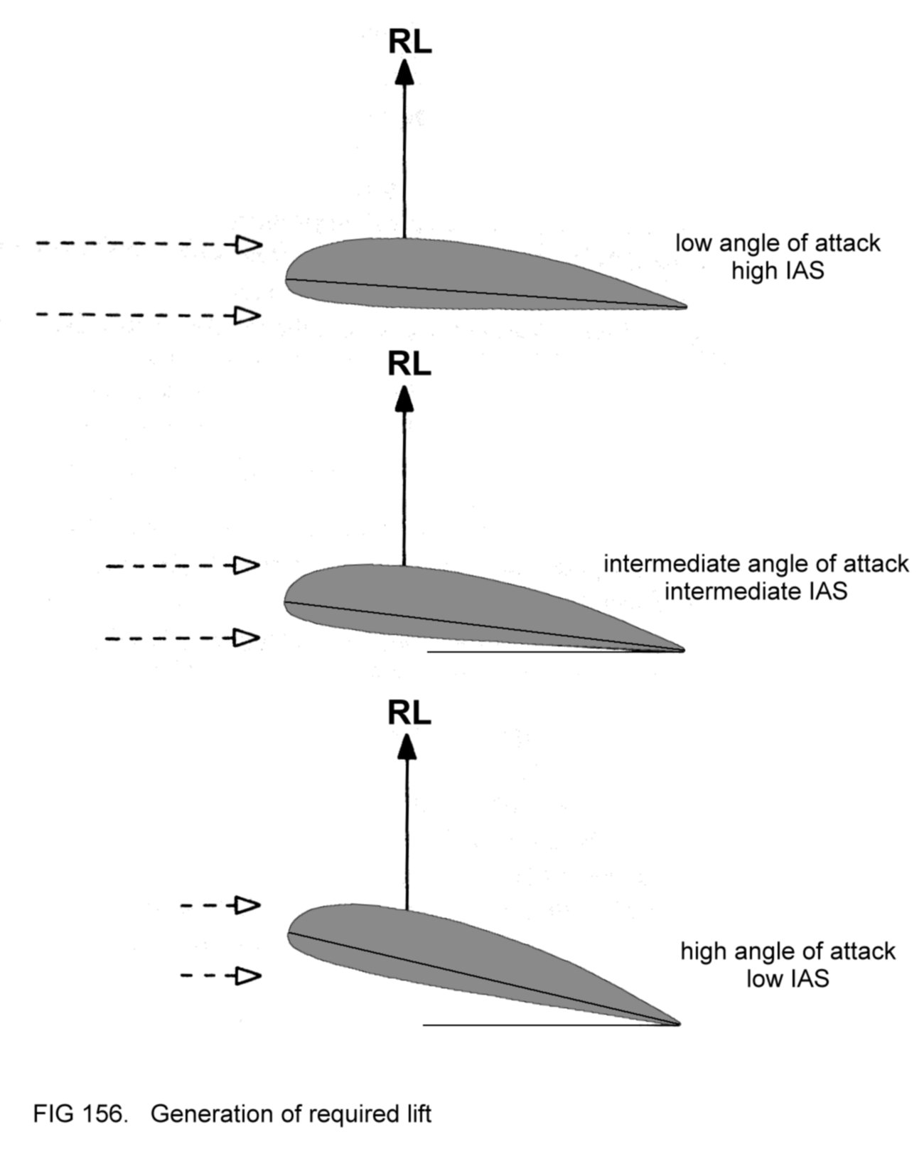
4.20.2
Control of flight
path with attitude
So far as the vertical
flight path is concerned, the aircraft's
behaviour is indicated to the pilot by the altimeter and VSI. In level
flight the altimeter shows constant height and the VSI no climb or
descent. Climbing flight is indicated directly by the VSI and as an
increasing reading on the altimeter. Descending flight is indicated
directly by the VSI and as a decreasing reading on the altimeter.
We have already seen
that, after the pilot has chosen any particular
power and altitude settings, the aircraft will take up a flight path
which disposes the five forces in equilibrium. Because of its inertia,
the aircraft tends to resist changes in its
flight path. Any change in attitude that the pilot might make will
therefore have the initial effect of altering the angle of attack of
the wings. In turn, the lift generated will change in magnitude, so
that it now differs from that required to maintain the original flight
path. The resulting imbalance will modify the flight path in such a way
as to match lift generated to that required to maintain the new flight
path, so restoring equilibrium.
As an example, consider
that the aircraft is in a descending flight
path, with its engine set to cruising power. (The IAS will be
relatively high, because of the effect of gravity assisting the thrust
from the propeller.)
Suppose that the pilot
pitches the nose up to a higher attitude.
Initially, the angle of attack will be increased, and the generated
lift will exceed that required. As a result the aircraft will adopt a
shallower descent path. The new flight path will decrease the angle of
attack again, lessening the lift generated to that required.
In the shallower descent
path there is less assistance from gravity in
opposing drag, with the consequence that the aircraft decelerates to a
lower IAS. (Assuming that required lift always has approximately the
same magnitude regardless of flight path, we can deduce that once the
aircraft has stabilised in the shallower descent its angle of
attack is greater than in
the steeper descent, because of the lower IAS.)
Adopting a higher
attitude again, the pilot might find that his
aircraft stabilises in a climb, in which situation gravity is opposing
the thrust from the propeller, resulting in an even lower IAS (and
hence higher angle of attack).
By trial-and-error, the
pilot will be able to find a particular
attitude somewhere between these latter two at which the aircraft
maintains constant height. For future reference, he will know that this
particular combination of power and attitude will always result in
level flight.
4.20.3
Control of speed
with power
In level flight an
aircraft's speed is controlled by the power
setting. In the example above, the combination of cruising power with
the attitude for level flight will result in the machine stabilising at
a particular IAS.
To fly level at any
other speed will require an adjustment in the power
setting. However, if the previous attitude is maintained, any change in
power will also result in the aircraft taking up a new flight path in
order to balance the forces again. In other words, this attitude will
not result in level flight if the power setting has been altered.
Suppose, for example,
that it is desired to fly at higher IAS. The
pilot's first action will be to increase power. As the aircraft
accelerates it will take up a climbing flight path in which the various
forces are disposed in equilibrium at the higher IAS. To re-attain
level flight, all that is needed is for the pilot to select a lower
attitude. If the new attitude is chosen correctly, level flight will be
achieved. (If the chosen attitude is not low enough, the aircraft will
continue to climb, but in a shallower flight path. If too low, the
machine will stabilise in a descent.)
The transition from
climb to level flight will result in a further
increase in IAS. Of course, the wings will now be at a lower angle of
attack than they were during level flight before the speed was
increased.
Conversely, level flight
at lower IAS will entail the choice of lower
power and higher attitude. Figure 157 shows what might be typical
attitudes for level flight at various speeds.

In practice, the pilot
will find that the attitude
change
corresponding
to a particular speed alteration (say, 20 knots) is greater in the
region of low IAS than in the region of higher IAS. This
phenomenon is
a result of aerodynamic factors and is illustrated in Figure
157.
With experience, the
pilot will be able to fly level at any chosen IAS
(within practical limits) by correct setting of power and attitude.
Note that the
longitudinal trim changes resulting from alteration of
power setting will be in opposition to the attitude adjustments needed
to maintain level flight.
For example, increasing
power will tend to cause pitch up at a time
when a lower
attitude
is required to maintain level flight at the
resulting higher IAS. The
pilot must use the control wheel to hold the
chosen attitude rigidly, against the opposing pitching effect.
Of
course, the trim wheel should then be used to eradicate the control
wheel force, so that the aircraft is re-trimmed in its new attitude.
4.20.4
Straight flight
Any tendency of the
aircraft to change its heading can only be caused
by the yaw arising from banked flight or from the misuse of rudder, or
by propwash induced yaw.
If, therefore, the pilot
ensures that the wings are level (using the
ailerons if necessary to make certain that this is so) and that the
flight is balanced (using rudder as appropriate to maintain a central
disposition of the ball in the balance indicator) then there can be no
yawing influence acting on the aircraft, and so it will maintain a
constant heading.
4.20.5
Balance
Suppose that the pilot
has correctly eliminated propwash-induced yaw,
but that he fails to keep the wings level. Perhaps he has inadvertently
selected a slight bank to the right. The aircraft will start to turn
to the right, of course. The pilot, instead of levelling the wings as
he should, might prevent the turning effect by applying left rudder.
(The turning motion is arrested because the action of the fin in
nullifying the bank-induced sideslip is opposed by the effect of the
airflow on the displaced rudder, as shown in Figure 158.)
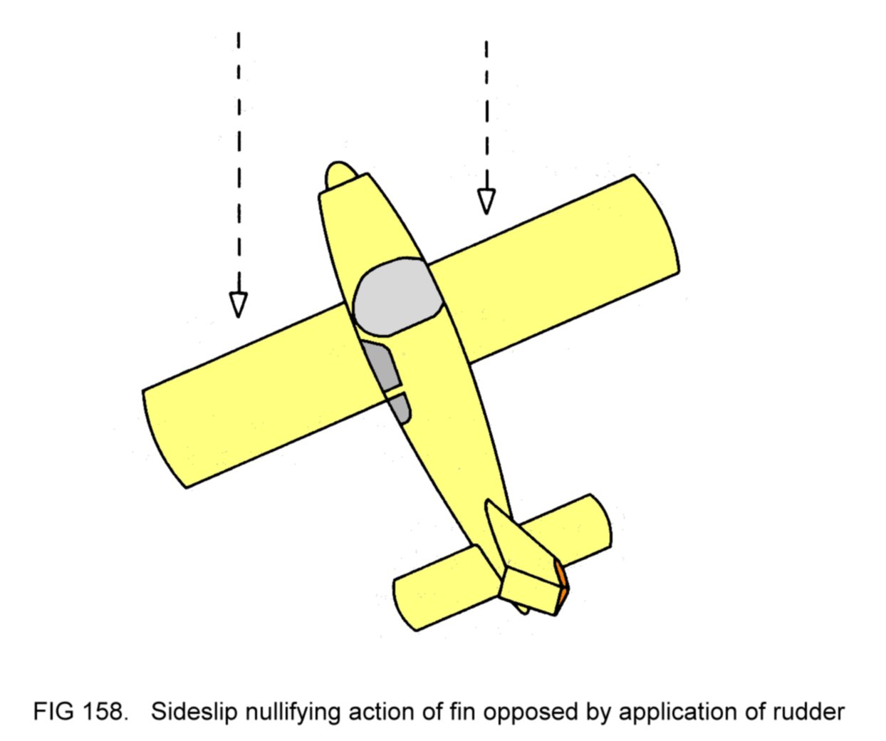
It will be agreed that
straight flight has indeed been
achieved as the
heading is not changing, even though it differs from the direction of
flight. Since the aircraft is not turning, the ball
in the balance indicator will take up its lowest position. Because of
the bank, however, the disposition will not be central (Figure 159).

Evidently the flight is
unbalanced. Note that, as a result of the
continuing sideslip, the aircraft's lateral stability will attempt to
roll it to the left. In other words, the bank can only be maintained
by holding the ailerons in their displaced positions with the control
wheel. The straight flight has been achieved
by the ailerons and rudder acting in opposition; this situation is
referred to as flight with 'crossed controls'.
We know that to rectify
the unbalance the right rudder pedal must be
pushed forwards, in accordance with the disposition of the ball in the
balance indicator. If this is done, thereby restoring the rudder to its
original position, and the wings are then levelled (using the
ailerons), the aircraft will again take up a straight flight path. Now
the flight will be balanced. (Not surprisingly, for a particular power
setting and pitch attitude, balanced straight flight will result in a
higher IAS than straight flight with crossed controls, since drag is
minimised.)
Although marked
unbalance is obvious to the pilot (because of the bank
attitude), slight unbalance may not be so. The correct technique,
therefore, is to use the rudder as dictated by the balance indicator,
and to concentrate on holding the wings level by appropriate use of the
ailerons.
4.20.6
Drag
It will be recalled that
the total drag generated by an aircraft is
made up of two contributions, namely turbulent wake drag (generated by
the entire machine) and induced drag (generated by the wings).
We know already that the
former increases with the square of the IAS.
For example, doubling the IAS results in turbulent wake drag increasing
to four times its magnitude.
At any particular angle
of attack, induced drag follows the same
relationship. Of course, induced drag is also affected by variation of
angle of attack.
At low IAS, the high
angle of attack needed to generate the required
lift causes high induced drag; the opposite is true at high IAS.
Obviously, the two factors (IAS and angle of attack) are in opposition
so far as the magnitude of induced drag in concerned. To determine the
overall effect, consider the 'effective lift force' generated in each
of the extreme situations shown in Figure
156. (Remember
that the effective lift force acts at right
angles to the direction of the
airflow in the downwash.) Figure 160 shows these forces resolved into
lift and induced drag.

We can deduce that
flight at low IAS incurs greater induced drag than
at high IAS
- the angle of attack factor predominates over
the IAS
factor.
In Figure 161 is shown
the variation of turbulent wake drag, induced
drag and total drag (the two contributions added together) with IAS.

The diagram shows that
there is one IAS at which the total drag has its
lowest magnitude. It is annotated Vmd (the IAS for minimum drag).
In level flight there
will be only one angle of attack that will
generate the required lift at Vmd. It is thus the angle of attack at
which the ratio of lift to total drag, in other words the aerodynamic
efficiency of the aircraft, is highest.
4.20.7 Power
It can be shown that the
power required to propel the aircraft in
level flight is the product of its total drag and its TAS. As an
equation:
Power = Drag x TAS
We shall consider the
case at sea level in the ISA (where TAS equals
IAS), in which:
Power = Drag x IAS
Reference to Figure 161
shows that selection of an IAS slightly less
than Vmd results in only a small increase in drag. In fact the increase
in drag is less than the reduction in IAS, in relative terms. In this
IAS range the product of drag and IAS is therefore less than at Vmd.
However, if IAS is reduced further, drag increases at a greater rate
than IAS decreases, and so the power required from the engine is
increased.
We can deduce that there
is an IAS at which minimum power is
required
(Vmp) and that this speed is less than Vmd. Figure 162 shows the
variation in power required with IAS.

In level flight there
will be only one angle of attack which will
generate the required lift at Vmp. Of course, at this angle of attack
the aircraft is not flying at maximum aerodynamic efficiency.
Note that flight at
constant IAS below Vmp requires increased
power. In
practice, the aircraft is not usually flown in this speed range. The
lowest IAS that can be maintained in level flight occurs when the wings
are just below the stalling angle of attack; flight at this speed
involves the use of a considerable amount of power.
The highest IAS that can
be maintained in level flight occurs when the
engine is delivering full power, with the aircraft in the appropriate
pitch attitude.
4.20.8 Flying
for maximum
range
For economy of
operation, it is highly desirable to be able to fly the
aircraft at the speed at which it travels the maximum distance, or
range,
through the air for each litre of fuel consumed.
We can determine this maximum
range speed
from the equation introduced
in 4.20.7. To recap:
Power required = Drag x
TAS
Each litre of fuel
enables the engine to deliver a certain amount of
power for a certain length of time. The two quantities are related; for
example, if the power output is doubled, it can be sustained for only
half the length of time. In other words, the product of power and time
is a fixed quantity, representing the work
obtainable
from the litre
of fuel for propelling the aircraft. We can re-write the equation as:
Power x Time = Drag x
TAS x Time
or
Work obtainable = Drag x
TAS x Time
The product of TAS and
time is equal to the actual distance travelled
through the air. (As an example, an aircraft flying at 2 nautical
miles per minute for 5 minutes travels 10 nautical miles.)
Our equation becomes:
Work obtainable = Drag x
Distance
or
Distance = Work
obtainable
Drag
Now, since it is known
that the work obtainable is a fixed quantity, we
can deduce that in order to maximise the distance flown, the
aircraft's drag must be
minimised.
We can conclude that the
maximum range speed is identical with the
minimum drag speed, Vmd.
In practical terms, for
a flight from one particular location to
another, total fuel consumed can be minimised by cruising at Vmd.
The IAS for maximum
range for any aircraft will be specified in its
Flight Manual.
4.20.8.1
Effect of height
on range
Since Vmd is concerned
with the aircraft's aerodynamic characteristics
and is expressed as an IAS, it is not affected by height. At the same
time, the TAS resulting from flight at this IAS increases with height.
It would seem, therefore, that the range obtainable from each litre of
fuel can be enhanced by cruising at the greatest height achievable by
the aircraft.
However, the equation in
4.20.7
informs us that the power required to
maintain any particular IAS increases with height, because TAS
increases. To fly at Vmd at greater height therefore requires more
power from the engine. If this is so, of course, our litre of fuel
will be consumed more quickly. So the increase in TAS is offset by the
reduced time for which it can be maintained.
In practice, the two
effects tend to cancel out each other, and the
range obtainable is not affected greatly by height. Nevertheless, an
aircraft's Flight Manual may specify an altitude (height above sea
level) at which range is maximised.
4.20.9 Flying
for maximum
endurance
Operationally, it may
occasionally be necessary to use fuel at the
lowest possible rate of consumption. Flight at the maximum
endurance
speed will
minimise the rate of consumption and so
maximise the length
of time for which the aircraft can fly for each litre of fuel
consumed.
The derivation of the
maximum endurance speed is straightforward if we
consider the litre of fuel as representing a fixed quantity of work
obtainable. In 4.20.8 we used the relationship:
Work obtainable = Power
x Time
or
Time = Work
obtainable
Power
In order to maximise
time, it is evident that the power
output from the
engine must be the lowest that will enable the aircraft to maintain
level flight.
In other words, the pilot must fly at the minimum
power
speed, Vmp.
In practice, flight at this speed is
impractical, since
there is no reserve for manoeuvring. For this reason, it is usual for a
factor of, perhaps, 5 knots or so to be added, giving the recommended
maximum endurance speed
that will be specified as an IAS
in the Flight
Manual.
4.20.9.1
Effect of height
on endurance
In 4.20.7 we considered
the case of power required with varying IAS at
sea level in the ISA. If we were to examine the relationship at greater
heights, the results would be as shown in Figure 163.

The diagram shows that
the TAS at which minimum power may be used is
increased at greater heights. In fact, at any chosen height, the
correct TAS for minimum power is achieved by flying at Vmp, which is
specified as an IAS.
However, since:
Power required = Drag x
TAS
it is not surprising
that Figure 163 shows an increase in minimum power
required in greater heights. Since the work obtainable is a fixed
quantity, therefore, the length of time for which flight may be
maintained is lessened. In other words, endurance is
reduced at greater
heights.
The conclusion is that,
to maximise endurance, the pilot should fly his
aircraft at the recommended maximum endurance speed at as low a
height as is compatible with adequate terrain clearance.
The reader will
appreciate that the recommended maximum endurance speed
is always less than the maximum range speed for any particular aircraft
(since Vmp is less than Vmd).
4.20.10
Technique for
straight and level flight
A summary follows in
practical terms of the various observations
concerning straight and level flight:
Level flight at any
chosen IAS is achieved by setting the correct power
and attitude.
IAS can be varied by
appropriate resetting of power; attitude is
adjusted as required to maintain level flight. When altering IAS, it
should be borne in mind that the aircraft takes time to accelerate or
decelerate, because of its inertia. The skilful pilot will be able to
make his attitude changes at such a rate that, at any instant during
the change in speed, the attitude matches the IAS, so that level flight
is maintained throughout.
When the correct
attitude for level flight is established the aircraft
should be trimmed to remove the control wheel force.
Straight flight is
achieved by holding the wings level and ensuring
that the aircraft is in balance.
Greatest range is
achieved by flight at the maximum range speed (and
optimum altitude) specified in the Flight Manual.
Greatest endurance is
achieved by flight at the recommended maximum
endurance speed similarly specified, at as low a height as is
practicable.
If time-saving is more
important than maximising range or endurance,
TAS can be increased by cruising at higher IAS or at greater height, or
both.
4.20.11
Correction of
deviations
Because of disturbances
in the air or inadvertent movement of the
controls by the pilot, it may well be that the aircraft deviates from
the desired heading and height.
Heading deviation may be
corrected by gently banking the wings in the
appropriate direction so that the machine turns towards the chosen
directional reference point (or the chosen heading indication on the
DI). When the correct heading is re-attained, the wings should be
levelled again to resume straight flight.
Excess height may be
corrected by temporarily selecting a slightly
lower attitude. (The ensuing increase in IAS may be prevented if
desired by a small reduction in power.) As the aircraft descends to
the chosen height, the attitude should be restored to its original
setting (and the power reset as appropriate if it was reduced) to
regain level flight.
Conversely, insufficient
height may be corrected by temporarily setting
a slightly higher attitude, preventing the resulting decrease in IAS
with a small increase in power. As the aircraft climbs to the chosen
height, the attitude and power should be readjusted to their original
settings to regain level flight.
4.21 CLIMBING
In straight climbing
flight the aircraft is made to climb at a
constant IAS on a constant heading.
It has already been seen
that certain combinations of power and
attitude will result in climbing flight. In practice, specific
combinations are chosen to optimise the aircraft's performance.
4.21.1
Climbing at
maximum rate
When climbing, the pilot
will often want to gain height as quickly as
possible. In other words, he will want to climb at maximum rate.
Figure
155 showed
that, in
climbing flight, thrust is greater than drag.
Alternatively, we can consider that the engine power output converted
by the propeller into thrust is greater than that required for level
flight at the same speed, with the excess of power responsible for the
gain in height.
The power converted into
thrust is that actually delivered by the
engine reduced somewhat by propeller inefficiency. For a fixed-pitch
propeller, efficiency varies with the aircraft's speed, as was
explained in 3.10.4.1, and
is usually highest in the cruising speed
range, when about 80% of the engine's propulsive force is converted by
the propeller into thrust.
The power available is
that converted into thrust when the engine is
delivering full power. Figure 164 illustrates the variation of power
available with IAS at sea level. Also shown is the variation of power
required to maintain level flight at sea level.

Some interesting
observations can be made:
(a) IAS (1) is the
lowest speed which can be maintained in level
flight, with the wings just below the stalling angle. (The power
required to maintain this speed is less than that available);
(b) at IAS (2) the
excess of power available over that required is
greatest. Thus flight at this speed with the engine at full power will
result in the aircraft achieving its maximum rate of climb;
(c) at IAS (3) the
propeller efficiency is greatest;
(d) IAS (4) is the
maximum speed which the aircraft can maintain in
level flight, with power available equal to that required. The machine
cannot climb at all at this speed, since there is no excess of power.
As already stated,
Figure 164 relates power available and power
required
to IAS at sea level. Obviously, in climbing flight the aircraft is
increasing its height, and these relationships will be changed as
height is gained. As a general rule of thumb for light aircraft, the
IAS which gives the maximum rate of climb at sea level should be
reduced by 5 knots for every 5000 feet of height gained, if maximum
rate of climb is to be maintained.
The power required to
maintain the appropriate IAS increases with
height, since TAS increases at a greater rate than the IAS is
decreased. At the same time, the power available is reduced, because
the engine's maximum power output decreases, as was explained in 2.2.6.
Hence the excess of
power,
and thus the maximum rate of climb, are reduced, until eventually a
height is reached at which, even with the engine at full power, the
aircraft can climb no higher. In other words, it has reached its
ceiling.
Another factor must be
considered, however, before deciding the best
speed at which to climb, namely engine cooling. When the engine is set
to full power it is difficult for the cooling fins to get rid of the
heat from the cylinders, especially at the relatively low IAS at which
the maximum excess of power occurs. (Remember that at low speed the
airflow through the fins is not strong.) With some aircraft designs,
it is necessary to prevent engine overheating by either increasing the
IAS, or by reducing power slightly, or both. Of course, either of these
actions will reduce the excess of power and hence the maximum rate of
climb.
An aircraft's Flight
Manual will therefore specify the recommended IAS
and power setting which should be adopted for maximum rate of climb.
For many smaller aircraft, it is permitted to climb with the engine
at full power so long as the oil temperature limitation is not
exceeded. To maintain maximum rate of climb as height is gained, the
rule of thumb given above should be applied to the recommended IAS.
Having set the specified
climbing power, the only means by which the
IAS can be controlled is by attitude.
In practice, an attitude is
selected which the pilot believes will result in the correct IAS. If
the aircraft stabilises at too high a speed, a higher attitude should
be tried, and vice versa. (Because of the aircraft's inertia, several
seconds elapse before the machine settles at a new speed after change
of attitude.) After some experience has been gained this
trial-and-error method will not be needed - the pilot will come to know
the attitude setting that will achieve the correct IAS. The rate of
climb will be indicated by the VSI.
Propwash-induced yaw
will be more marked in the climb, because of the
use of high power. Application of rudder will be needed to keep the
balance indicator ball centred. If this is done, and the wings are held
level, then the aircraft will climb on a constant heading. Figure 165
shows what might be a typical climbing attitude.

Note that the view ahead
of the nose is restricted by the engine
cowling. To verify constancy of heading a directional reference point
can be chosen to the side of the cowling, as shown. Alternatively,
consultation of the DI will serve the same purpose.
The restricted view
ahead also denies to the pilot the ability to watch
for the presence of other traffic. This problem can be overcome by
banking the aircraft gently to one side (for example, to the
right) for a few seconds to change heading, so that the area in
question is brought into view to the side of the cowling. Having
satisfied himself that there is no conflicting traffic, the pilot can
then bank the machine back to the original heading. This procedure
should be repeated from time to time.
Periodically, during a
prolonged climb, the oil temperature should be
checked. If the gauge reading approaches the maximum permitted, power
should be reduced to prevent overheating. (In the climbing attitude,
reduction of power will cause the aircraft to decelerate - the correct
IAS can be maintained by setting a lower
attitude.)
Alternatively, or
additionally, a lower attitude again can be set to give a higher IAS
and so assist with cooling. Either of these actions will detract from
the maximum achievable rate of climb.
Notice that the
aircraft's controls are being used in a different
manner compared to level flight. In
the climb, the power setting is
fixed and IAS is controlled by attitude.
The transition from
climb to level flight when the aircraft has
reached the desired height is termed 'levelling off'. The normal
technique is firstly to lower the nose gradually to the cruising
attitude. The aircraft will then accelerate. As the desired cruising
speed is attained the power should be reduced to the correct setting so
that this speed is maintained in level flight. If the first attempt
does not result in exactly the required behaviour, further adjustments
of power and attitude are made until the aircraft is flying level at
the chosen speed. Since the flight path cannot be changed immediately,
because of the machine's inertia, the levelling off process should be
initiated just before the chosen height is reached. If the anticipation
is judged correctly, level flight will be achieved at exactly this
height.
4.21.2
Climbing at
maximum gradient
The gradient of
climb
is the ratio of height gained to horizontal
distance travelled in a given time. It can be considered as the angle
at which the flight path is inclined (Figure 166).

Suppose that the
aircraft is climbing at maximum rate, and that the
pilot then raises the nose to a slightly higher attitude. The effect
will be to reduce the IAS. In consequence, the horizontal distance
travelled through the air in a given time will be reduced. Although at
this lower IAS the power excess will be less, it will not be very much
so, as reference to Figure 164 confirms. In other words, the reduction
in rate of gain of height is less than the reduction in horizontal
distance travelled, in relative terms, and so the gradient of climb
will be steeper.
Of course, if the speed
is reduced too much the rate of climb will
lessen considerably (because of the smaller power excess) and so the
gradient of climb will be reduced. We can conclude that there is one
IAS at which maximum
gradient of climb
is achieved, and that this speed
will be slightly lower than that for maximum rate of climb (and
correspondingly, the attitude slightly higher).
Figure 167 illustrates
the two cases, representing 1 minute's flight.

In practice, the
aircraft is made to climb at maximum
gradient when obstacles obstruct the flight path after take-off. For
this reason, the technique is sometimes referred to as 'obstacle
clearance climb'. The reader will appreciate that prolonged climb at
maximum gradient IAS may cause engine overheating problems, and so it
is normal practice to revert to maximum rate or cruise climb (described
later) as soon as the obstacles have been safely overflown.
The aircraft's Flight
Manual will specify the IAS at which maximum
gradient of climb is achieved.
4.21.3
Summary of
techniques for climbing
From level flight, climb
at maximum rate is achieved by firstly setting
climbing power (maximum if permitted) and then adopting the pitch
attitude which results in the IAS recommended in the Flight Manual. The
aircraft should be
trimmed in this attitude.
Constancy of heading is
achieved by balancing the flight with
appropriate application of rudder and by holding the wings level.
Banking the aircraft occasionally to change heading temporarily will
enable the pilot to see any other traffic in the intended flight path.
During a prolonged climb
close watch must be kept on the oil
temperature gauge. Appropriate action should be taken if necessary to
prevent the maximum permitted temperature being exceeded.
To level off, the nose
is lowered to the cruising attitude and the
power reduced to the corresponding setting once the IAS has increased
to that desired. When level flight has been attained the aircraft
should be re-trimmed.
Maximum gradient of
climb is achieved by setting climbing power and
adopting the attitude which results in the IAS specified in the Flight
Manual. As soon as possible the pilot should revert to maximum rate
climb or cruise climb.
4.21.4
Cruise climb
If it is necessary to
increase height, and rate or gradient need not be
maximised, the usual technique is the cruise climb. In
the cruise climb
the power setting is somewhat higher than during level cruising but
less than maximum, and the attitude is set for an IAS between that for
maximum rate climb and that for level cruising, according to the
pilot's preference. Besides conferring the advantage of higher speed,
the lower attitude also offers a better view ahead of the aircraft.
The levelling off technique is as already described.
4.22
DESCENDING
In straight descending
flight the aircraft is made to descend at a
constant IAS on a constant heading.
As already stated,
certain combinations of power and attitude will
result in descending flight. In practice, specific combinations are
used, depending on the required descent path. Descending with the
engine at minimum power is referred to as 'gliding'.
4.22.1
Gliding at minimum
gradient of descent
The gradient of descent
is the ratio of height lost to horizontal
distance travelled in a given time. It can be considered as the angle
at which the flight path is depressed (Figure 168).
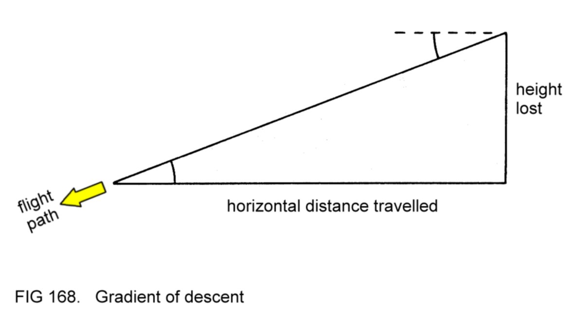
Occasionally, it may be
necessary for the pilot to glide his aircraft
at minimum
gradient of
descent.
Figure
155 showed
that, in
descending flight, thrust is less than drag.
With the engine at minimum power, thrust is reduced almost to zero. In
this
situation gravity alone
(in other words, the weight force) enables the aircraft to maintain
constant IAS, with the forces disposed as in
Figure 169. (The dotted arrow shows the
component of the weight force which opposes drag.)
When the aircraft is
gliding its gradient of descent is entirely
dependent upon the ratio of required lift to total drag, as reference
to Figure 170 will confirm.

Notice that, the greater
the ratio of lift to total drag, the shallower
is the gradient and so the greater is the horizontal distance
travelled for any particular height reduction. Since the required lift
is approximately constant regardless of the descent path, we can
conclude that the
minimum gradient occurs when the aircraft is
gliding with its wings at the angle of attack at which minimum total
drag occurs.
The aircraft's Flight Manual will quote the
gliding IAS which
corresponds to this angle of attack. (In practical terms this speed
will equal the speed for maximum
range,
which also implies flying at the speed which maximises the ratio of
lift to total drag.)
With the engine at
minimum power, the only means by which the IAS can
be controlled is by attitude.
Too high an attitude will result in too
low an IAS, and vice versa. With experience, the pilot will know
exactly which attitude achieves the correct IAS.
Since the IAS for
minimum gradient gliding is in the lower speed range,
the pilot will find that the corresponding attitude is not markedly
low. In fact, with many aircraft designs, the correct attitude is not
much lower than that for cruising in level flight at higher IAS. With
this being the case, it will be appreciated that the view of the area
into which the aircraft is descending is obscured by the engine
cowling. The problem can be overcome by temporary changes of heading
during the descent, so that the area in question is visible to the side
of the cowling.
Note that gliding at any
other than the specified IAS, either
faster or
slower, will result in a steeper descent. In the latter case, we have a
clear example of a situation in which the vertical flight path of the
aircraft is not in the same direction as the nose is pointing,
because a relatively high angle of attack is involved. Figure 171
illustrates.

Propwash-induced yaw
will be virtually non-existent during the glide.
If the rudder trim tab has been set for cruising flight, therefore, the
aircraft will tend to fly out of balance. Application of rudder in
accordance with the balance indicator will rectify the situation. (Of
course, the application will be the opposite to that needed during the
climb, when the engine is at high power.)
Periodically during a
prolonged glide, the engine should be opened up
to cruise power for a few seconds. This action is called 'clearing the
engine' and serves two purposes. Firstly, it ensures that any oil film
which has formed on the spark plug electrodes is burnt away.
Secondly, it prevents the engine and oil from cooling too far below
the normal operating temperature.
Levelling off from
descent to level flight is initiated as the aircraft
approaches the desired height. From the glide, the usual
technique is firstly to set cruising power, whilst maintaining the
descent attitude. The aircraft will then accelerate. As the desired
cruising speed is reached the nose is then raised to the corresponding
attitude, so that level flight is established. If the first attempt
does not result in exactly the desired behaviour, further adjustments
of power and attitude are made to achieve level flight at the chosen
speed.
The levelling off
process should be initiated just before the chosen
height is reached, so that level flight is achieved at exactly this
height.
4.22.2
Sideslipping
Occasionally, the pilot
may wish to glide more steeply than the minimum
gradient. There are several methods of doing so available to him.
Firstly, by a suitable
adjustment of attitude, he can fly at a faster
IAS than that for minimum gradient. This technique will not be suitable
if approaching to land, however, since the pilot will not want
excessive speed at this stage.
Alternatively, he could
fly at a slower IAS than that for minimum
gradient, but this procedure reduces the effectiveness of the flying
controls and involves the wings meeting the airflow at an angle of
attack close to the stalling angle, and so is usually avoided.
Since the gradient of
descent depends on the ratio of lift to total
aircraft drag, it can be appreciated that, in order to steepen the
descent path without departing from the normal (minimum gradient)
gliding speed, extra
drag must be created.
If flaps are fitted to the aircraft,
lowering them will have this effect and will therefore
achieve the desired result. (We shall look at use of the flaps in more
detail later.)
A few designs of
aircraft do not incorporate flaps. If the pilot
wishes to steepen the glide without increase or decrease of speed, he
can resort to sideslipping. The technique involves deliberate
unbalanced flight using crossed controls, to generate extra drag.
For example, suppose
that left bank is applied, using the ailerons, and
the consequent yaw prevented by application of right rudder, so that
straight flight (constant heading) is maintained. Appropriate lowering
of pitch attitude to prevent the extra drag from slowing the aircraft
will enable the normal
gliding speed to be maintained.
Note that, when
sideslipping, the aircraft's flight path, although
straight, is not in the same direction as its heading. Figure 172
illustrates the example above - sideslipping to the left.

The amount of bank that
can be set (and hence the steepness of descent)
is limited by the effectiveness of the rudder. When maximum deflection
of the latter is required to maintain straight flight, any further
application of bank will cause vaw in the direction of the bank.
When desired, balanced
flight can be restored by centralising the
rudder and levelling the wings. With the extra drag removed, a slightly
higher pitch attitude will then be needed to prevent acceleration above
normal gliding speed.
Sideslipping to the
right involves left rudder opposing right bank.
4.22.3
Powered descent
In the glide at minimum
gradient IAS the aircraft will stabilise at a
steady rate of
descent,
indicated by the VSI. If it is desired to
descend at a shallower gradient at this IAS, the rate of descent must
be decreased. Of course, the only way to achieve this is with the
assistance of engine power. If the glide attitude is maintained, any
increase of power will tend to accelerate the aircraft. To maintain
the original speed, therefore, a higher
attitude
will be required. The
new combination of power and attitude will result in a lower rate of
descent, and thus a shallower descent gradient. The aircraft is now in
a powered
descent.
Further increases of
power (and corresponding raising of pitch
attitude) will give even lower rates of descent and shallower
gradients. (The reader will agree that if the process is repeated
sufficiently, the aircraft will finally achieve a climbing flight
path.)
Notice the manner in
which the controls are being used, with power
controlling the rate of descent and attitude controlling the IAS.
4.22.4
Summary of
techniques for descending
From level flight at
cruising speed, gliding at minimum gradient is
achieved by firstly reducing power to minimum and maintaining attitude
until the IAS has decayed to that specified, and then lowering the
attitude as necessary to maintain this speed. The aircraft should be
trimmed in this attitude.
Constancy of heading is
achieved by balancing the flight and
holding the wings level. Banking the aircraft occasionally to change
heading temporarily will enable the pilot to see any other traffic in
the intended flight path.
During a prolonged glide
the engine should be cleared periodically.
To level off, the power
is increased to the appropriate cruise setting
and the nose is raised to the corresponding attitude when the
IAS has increased to that desired. When level flight has been attained,
the aircraft should be
re-trimmed.
If required, the
steepness of the descent path may be increased by
either gliding at higher IAS or, if increase of speed is undesired, by
lowering the flaps or by sideslipping.
In a powered descent
adjustments of engine power are used to control
the rate of descent and attitude is set as necessary to maintain the
correct IAS.
4.22.5
Cruise descent
If during cruising
flight it is desired to descend to a lower height
without change of speed, the usual technique is to reduce power and
adopt a lower attitude. The control technique is the same as during the
powered descent described above, with power set according to the
required rate of descent and attitude adjusted as necessary to maintain
cruising speed. To level off, the pilot should reset cruising power and
corresponding attitude.
4.23 FLAPS
The flaps are used to
alter the lift- and drag-generating abilities of
the wings. On many light aircraft, the flaps can be set either up or
down, or to an intermediate, 'maximum lift' position.
Refer back to Figure
5. Let us
consider the situation in
which the wing is moving through the air at the same speed and angle of
attack in each of the three flap configurations. (Note that the 'flaps
up' chord line is the reference for assessing the angle of attack at
other flap positions.) The overall camber of the wing is increased when
the flaps are lowered, as the diagram shows.
Compared to the 'flaps
up' case, the wing generates more lift in the
'maximum lift' flap configuration, because of the increased camber, and
slightly more drag. (Nevertheless, the ratio of total lift to total
wing drag, in other words wing efficiency, is decreased.)
In the 'flaps down'
configuration, lift is further increased slightly,
and drag considerably. (This being so, the reader will appreciate that
the term 'maximum lift' at the intermediate flap position, although
common parlance, in incorrect. The misnomer arises from the manner in
which the flaps are used.)
The flaps serve two main
functions. Firstly, in the 'maximum lift'
position, they reduce the length of runway needed for take-off. The
explanation is straightforward: at any particular angle of attack, the
required lift can be generated with the flaps in this position at a
lower speed than if they were up. If the aircraft's wings are at the
take-off angle of attack, then, the machine will leave the runway at a
lower speed, thereby using less runway distance during the take-off
acceleration. After the aircraft has become airborne, the lowered
flaps are a liability, because of the reduced wing efficiency. They are
therefore raised to the 'up' position to get rid of the extra drag, so
that the aircraft's subsequent climb performance is not impaired.
The second function of
the flaps is to increase drag, so that steep
descents may be made without the need to increase speed. Of course, for
this purpose they are lowered to the 'down' position. (At any
particular descent speed, the wings will be at a lower angle of attack
than with the flaps up, since the required lift is the same in both
cases. The lower angle of attack eradicates the increase of lift that
the flaps would otherwise confer.)
4.23.1
Effect of flaps on
stalling speed
When the aircraft is in
flight, the required lift can be generated at
high speed with the wings at low angle of attack, or vice versa. In the
latter case the limit is reached when the angle of attack has increased
to the stalling angle. The IAS at which this situation occurs is called
the stalling
speed.
The aircraft stalls
when it slows to the stalling speed. To the pilot
the main symptoms are partial or complete loss of roll and pitch
control and loss of height, all these consequences arising from the
disruption of the airflow over the wings. Thus flight near the stalling
speed is generally avoided.
Consider the aircraft
just at its stalling speed with the flaps up. Of
course, the required lift can be generated at this same speed at a
lower angle of attack
if the flaps are at the 'maximum
lift' position.
If now the angle of attack is increased slightly, the required lift can
be generated at a slightly lower IAS, without the
occurrence of
stalling. A
further increase in angle of attack will,
however, result
in stalling, which will occur at a lower angle of attack than with the
flaps up. Nevertheless, the stalling speed will be less than before.
A further small
reduction in stalling speed results when the flaps are
fully down.
So far as practical
flight is concerned, the pilot may fly safely at
slightly lower speeds with the flaps lowered than he could with them
up, without erosion of the margin above the stalling speed.
4.23.2
Effect of flaps on
trim
Figure 173 shows the
flaps lowered to the 'maximum lift' position on
both a low-winged and a high-winged aircraft. It will be assumed that
the machines were trimmed in the attitudes illustrated before
the flaps
were lowered.

As already stated, the
wings generate more drag in this configuration.
In the case of the low-winged aircraft, reference to Figure 173
suggests that the extra drag will tend to make the nose pitch down. In
the other, a pitch up is more likely.
The lowered flaps also
have the effect of deflecting the downwash
further downwards, which in both cases will increase the tail
down-force, thus tending to cause pitch up.
We can conclude that
lowering the flaps on a high-winged aircraft will
cause the nose to pitch up, since the two effects just described are
acting in conjunction. On a low-winged machine, they are acting in
opposition. Whether pitch up or pitch down occurs depends on the
relative magnitudes of the two
effects. (On some designs they cancel out each other exactly.)
The pitching effect of
lowered flaps is evidently a trim change,
because the aircraft will tend to depart from the original trimmed
attitude. It can be prevented by appropriate use of the control wheel,
and the control wheel force then eliminated with the trim wheel. Moving
the flaps fully down will incur a further trim change.
Once the aircraft has
been trimmed with flaps down, raising them will
cause a trim change opposite to that when they were lowered. Again, the
effect can be prevented using the control wheel, and the machine then
re-trimmed.
4.23.3
Control of speed
and vertical flight path
If no change is made in
power or attitude when the flaps are lowered,
the extra drag will result in a reduced IAS. To achieve a desired
vertical flight path and the IAS appropriate to it after lowering the
flaps, then, adjustments of power and attitude may be needed. In fact,
the aircraft's controls are used as already described. In descending
flight, for example, an attitude is set which results in the
appropriate IAS, and power to achieve the required rate of descent.
(Note that, depending on
the design of the aircraft, the trim change
arising from lowered flaps may either assist or oppose the attitude
adjustment necessary to obtain the desired aircraft behaviour. The
correct attitude should be held rigidly whilst the trim wheel is used
to eradicate any control wheel force, so that the aircraft is
re-trimmed in the chosen attitude.)
Similar power and
attitude adjustments are made as necessary to achieve
the desired vertical flight path and IAS when the flaps are raised, and
the aircraft is again re-trimmed.
The flaps must never be
lowered at speeds in excess of the flap
limiting speed, otherwise they may be damaged by the airflow. Of
course, once the flaps have been lowered, this speed must not be
exceeded until they are raised again.
4.23.4
Effect of flaps on
forward view from cabin
As we have already seen,
the wings are at a lower angle of attack when
the flaps are lowered than at the same IAS with them up. As a
consequence, the aircraft's nose will be pointing more in the
direction of its vertical flight path, especially in the lower speed
(higher angle of attack) range in which climbing and descending flight
usually take place. Figure 174 illustrates the effect in descending
flight. Remember that both aircraft have the same IAS.
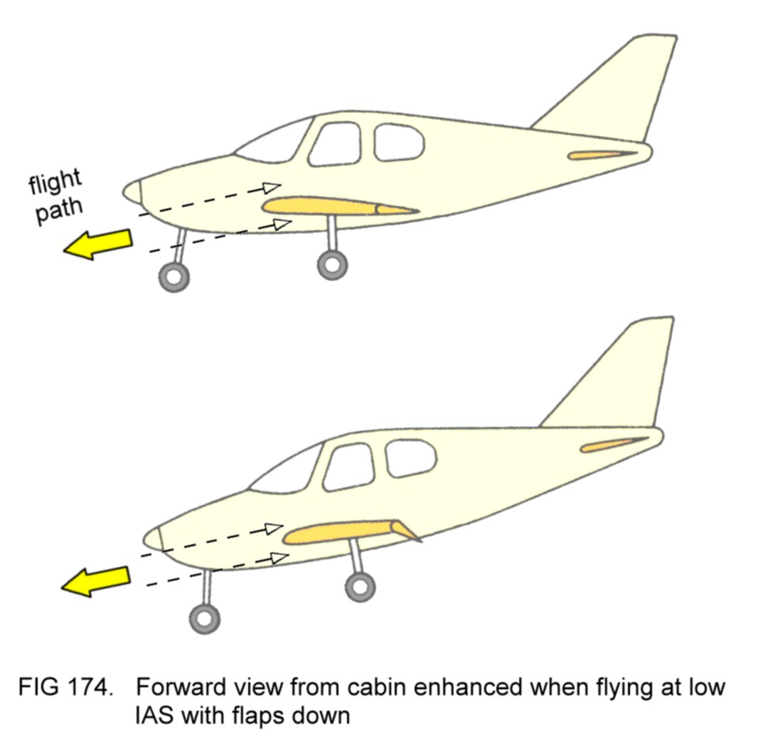
So far as the pilot is
concerned, when flying at low speed he has a better view of the
area into
which his machine is flying when the flaps are in use, with his vision
unobstructed by the engine cowling.
4.23.5
Use of flaps for
take-off
As already stated, the
aircraft's runway distance requirement can be
reduced by taking off with the flaps at the 'maximum lift' position.
Once the machine is
airborne, the flaps impair the climbing
performance, because of the extra drag. However, if they are raised
immediately
after leaving the ground, the consequent loss of lift may result in the
aircraft
sinking back to the ground. Additionally, the pilot will possibly have
to cope with a trim
change during a critical phase of flight.
For these reasons, the
flaps are not normally raised until the aircraft
has attained a safe height. To minimise the performance loss
before the flaps are raised, it is usual practice for the pilot to
climb at a lower IAS than
that for maximum rate of climb with flaps up, thereby gaining two
advantages. Firstly, the gradient
of climb is
better than at the higher
speed, because of the reduction in horizontal distance travelled.
(However, the gradient will not be as steep as at maximum gradient IAS
with the flaps up, because of the extra drag.) Secondly, since the
aerofoil shape is more highly cambered, the reduction in wing
efficiency
(in other words, the magnitude of the extra drag) is less at the lower
speed.
The aircraft's Flight
Manual will usually specify the optimum climbing
IAS to be used when the flaps are at the 'maximum lift' position.
Once a safe height has
been reached the flaps can be raised (which may
cause temporary sinking of the aircraft) and the attitude adjusted as
necessary to achieve the recommended IAS for maximum rate of climb.
4.23.6
Use of flaps for
approach and landing
The usual technique for
flying the aircraft towards the runway for
landing is the powered
approach,
in which the flaps are fully down and
the speed and vertical flight path are controlled by variations in
attitude and engine power
setting. (We'll look at this procedure in more detail
later.)
It seems illogical, at
first sight, to have the power (which reduces
the rate of descent at any particular approach speed) opposing the
effect of lowered flaps (which increases it). In fact this technique
confers three advantages over descent with flaps up.
Firstly, at the approach
speed, the range of rates of
descent is
broadened. With minimum power set, the gradient is considerably steeper
than with flaps up, if such a flight path is desired. With increasing
power, the same IAS will give shallower descent if needed.
Secondly, the pilot will
have a better view of the approach path.
Thirdly, the lowered
stalling speed makes possible safe reduction of
approach speed just prior to landing, so that, when the aircraft
actually touches down, it will run a shorter distance along the runway
while being braked to taxying speed.
The aircraft's Flight
Manual will specify the IAS at which the powered
approach should be flown. Usually, this speed is slightly less than the
normal gliding speed.
It may be that the pilot has to
break off his approach and climb away
again. This procedure is called 'going around' (Figure 175).
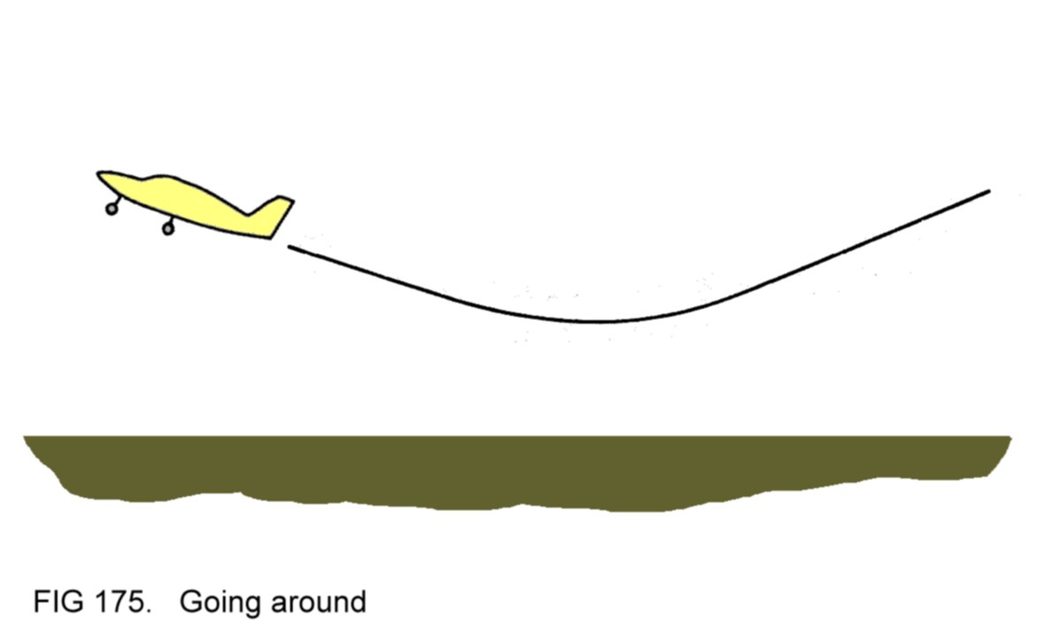
With the flaps fully
down, of course, the aircraft's climb performance
will be considerably impaired. However, raising the flaps will cause
the machine to sink, with possibly hazardous consequences if it is near
the ground, and there may also be a trim change.
Normal technique,
therefore, is firstly to establish a climbing flight
path with the flaps still fully down. Full power should be set and an
attitude chosen which gives an IAS at, or slightly below, that
specified for climbing with the flaps at 'maximum lift', to optimise
the gradient. As soon as a climb is established the flaps should then
be raised to 'maximum lift' and the attitude adjusted as necessary to
achieve the specified IAS.
At a safe height the flaps can be fully raised and maximum rate climb
established.
This technique of
raising the flaps in two 'stages' (that is, to
'maximum lift' first and then fully up at a safe height) divides the
attendant sink and trim change into more manageable quantities.
Likewise, the resulting increase in stalling speed occurs as two
smaller rather than one large increment.
4.24 MEDIUM
TURNS
In medium turns, the
aircraft is made to turn using angles of bank of
30° or less. Turns can be carried out in level flight, or when climbing
or descending.
4.24.1
Level turns
A turn made in level
flight is a level
turn. In
4.17.3
it was explained
that application of bank is a more efficient manner of turning than
application of rudder, because the latter results in skidding,
unbalanced flight.
Figure
117 showed
that in a
banked attitude the consequence
of the interaction of the weight force and the tilted lift force is
sideslip. The action of the fin in nullifying the sideslip then causes
the turning effect. Referring again to Figure 117, it will
be appreciated that, because the lift force is tilted, its vertical
component will now be less in magnitude than it is with the wings
level, as the top image in Figure 176 shows.

As a consequence, the
aircraft will not be able to maintain level
flight and will take up a descending flight path. To prevent this
occurrence, it is necessary to Increase the lift force so that its
vertical component equals the 'wings level' lift force, as shown in the
bottom image in Figure 176.
Of course, the lift
increase can be generated either by an increase in
speed or by an increase in angle of attack. In practice,
the latter method is chosen because it is more convenient for the
pilot. Reference to Figure 143
shows that when the aircraft yaws as a consequence of bank, its pitch
attitude becomes lower. The effect will be apparent to the pilot as a
lowering of the engine cowling below the horizon. By moving the control
wheel backwards to maintain the original pitch attitude, the pilot will
be arranging that his wings meet the airflow at the higher angle of
attack needed to generate the increased lift force.
Besides the lift
increase, the wings will also generate more drag at
this higher angle of attack. Consequently the aircraft will decelerate
to a lower IAS. The resulting decrease in lift will need to be offset
by a further small increase in angle of attack. So far as the pilot is
concerned, it is merely
necessary to adopt whichever pitch attitude achieves level flight.
In medium turns, the
pitch attitude differs little from that in level
straight flight at the same engine power setting, and the decrease in
IAS is not great (less than 10 knots for most light aircraft designs).
Figure
50 shows
typical attitudes for level turns using 30° of bank. Note that the
attitude in the turn to the right appears slightly lower than in that
to the left, because the pilot's seating position is on the left-hand
side of the cabin.
In practice, the pilot
will find that a slight back pressure is needed
to hold the control wheel in the position required to maintain the
correct attitude for level flight during the turn. It is normal
procedure not to use the trim wheel to eliminate this force, since the
turn is only a temporary manoeuvre. When the desired heading has been
attained, the wings are levelled to restore straight flight, in which
the back pressure will no longer be needed.
4.24.1.1
Balance: use of
rudder
In 4.12.2 it was explained
that when the control wheel is moved to the
left to apply bank, the ailerons are displaced in such a way as to
increase the lift at the right wing tip and to decrease that at the
left. The lift variation will entail a corresponding drag variation.
In other words, the drag at the right wing tip will be greater than
that at the left. As a result, the tendency of the aircraft to yaw to
the left under the sideslip-nullifying action of the fin will be
hindered by the opposite yawing effect arising from the difference in
wing tip drag. Figure 177 illustrates the situation.
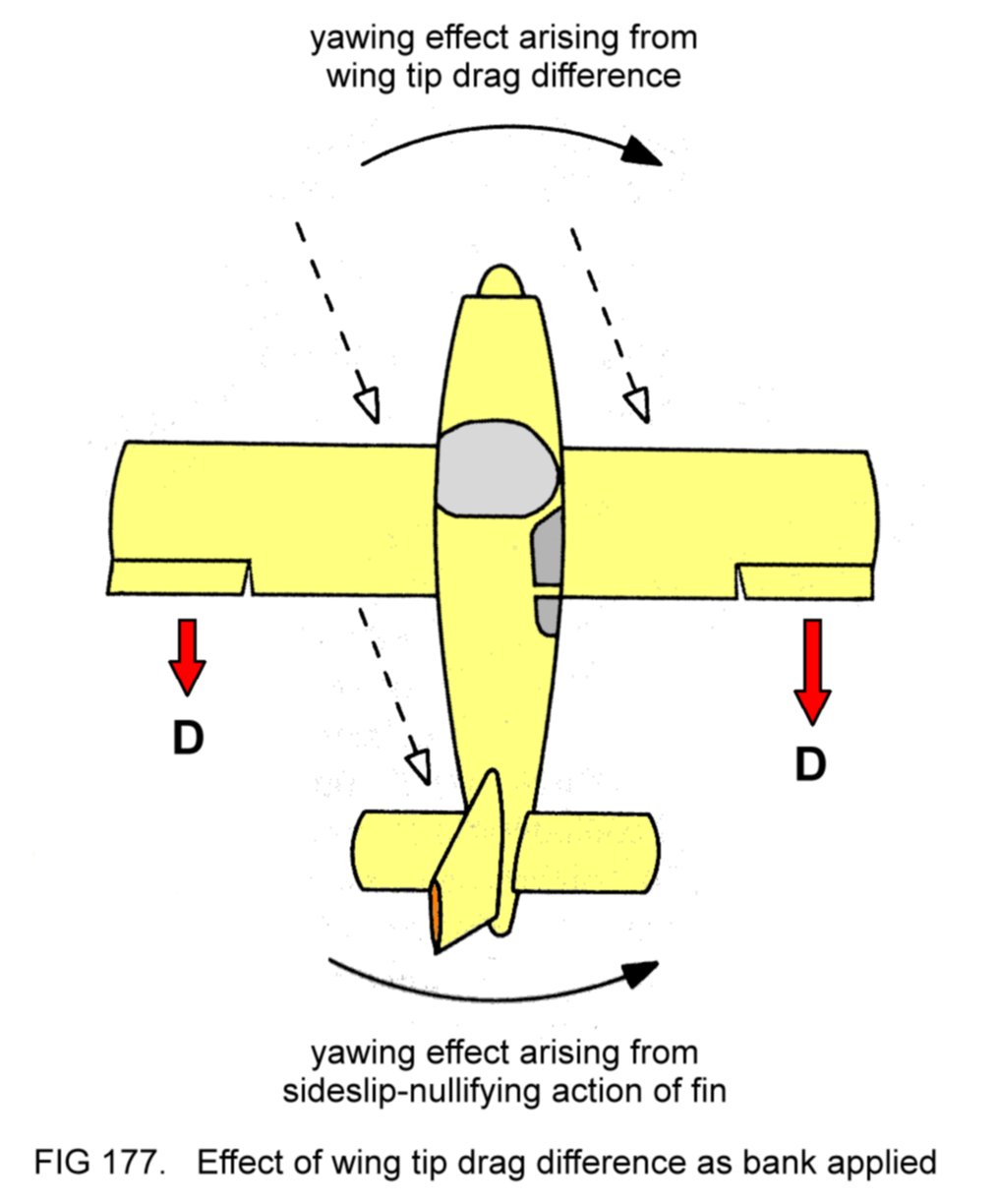
While the bank is being
applied, then, the desired turning motion of
the aircraft will be delayed. Meanwhile, the balance indicator ball
will
remain in its lowest position, showing unbalanced flight (Figure 178
top image).

Once the desired angle
of bank has been attained, of course, the
ailerons are centralised. This action will restore equality of lift and
drag at the wing tips. Now the yawing action of the fin will be
unhindered and the aircraft will
turn to the left. The ball will be thrown outwards, adopting a central
position in the indicator and so confirming balanced flight (centre
image).
When the control wheel
is moved to the right to level the wings after
completion of the turn, an opposite sequence of events occurs, with the
aircraft continuing to yaw under the influence of the wing tip drag
difference. The result is a transient state of unbalanced flight,
during which the balance indicator will be as in the bottom image.
The adverse yawing
effects occurring when the control wheel is moved
can be overcome by suitable use of the rudder. When the control wheel
is
moved to commence a turn to the left, simultaneous application of left
rudder will overcome the adverse yaw. Similarly, movement of the
control wheel to the right to level the wings after completion of the
turn should be matched with simultaneous application of right rudder.
Note that these rudder applications are as demanded by the balance
indicator. Identical considerations apply to the case of initiating and
completing a turn to the right. In conclusion, it can be stated that
whenever
the ailerons
are being used to roll the aircraft, sufficient
rudder should be applied in the same direction as the control wheel
movement to maintain balanced flight.
Most light aircraft are
designed to have good directional stability,
so that in turning flight the airflow past the fuselage is symmetrical
without the need for application of rudder. If the directional
stability is weak, the machine will tend to sideslip
slightly in the turn. The balance indicator will confirm the unbalance,
showing that application of rudder in the direction of the turn is
needed to rectify the situation.
4.24.1.2
Rate of turn
The concept of rate of
turn was introduced in 2.6.13.1.
At any
particular IAS, the rate of turn depends on the angle of bank. The
greater the angle of bank, the larger in magnitude is the
sideways-acting force arising from the tilting of the lift force, and
so the greater is the rate of turn. At a speed of 100 knots IAS, about
15° of bank is required for a rate 1 turn. A rate 2 turn requires about
30°. At higher speeds, greater angles of bank are needed to achieve
these rates of turn. (For example, about 20° is needed for a rate 1
turn at 150 knots IAS.)
Since the aircraft will
turn whenever bank is applied (assuming that
the flight is balanced), it will be understood that anticipation is
necessary when completing a turn onto a desired heading. If the pilot
maintains his bank until the chosen heading is attained, the aircraft
will continue to turn while he levels the wings. Straight flight will
only be restored after the wings have been levelled, by which time the
machine will have turned past this heading. The problem is overcome by
commencing the wing-levelling action just before the desired heading is
reached.
4.24.2
Climbing turns
The climbing turn
differs from the level turn in that the pitch
attitude is adjusted as necessary to maintain the chosen climbing
speed. Again, the wings are generating more lift, and drag, than in
straight climbing flight. The increased drag will tend to decelerate
the aircraft to a lower IAS. This effect can be prevented by adopting
a slightly lower pitch attitude than for the straight climb. In
practice, it will be found that, compared to level turns at the same
angle of bank, less back pressure wil be needed to hold the control
wheel in the correct position during climbing turns. This is because
the natural tendency of the pitch attitude to become lower in turning
flight will assist in the adoption of that required to maintain IAS.
Note that the greater
the angle of bank, the greater is the increase in
wing drag, and so the lower the pitch attitude must be to maintain the
chosen climbing speed.
The extra drag detracts
from the aircraft's climb performance. In
specific terms, the rate of climb at any particular IAS will be reduced
during turning flight. For this reason, it is usual practice to
restrict the angle of bank to 15°, so that the performance loss is
minimised.
Besides preventing
propwash-induced yaw, the pilot will need to use his
rudder to counteract the wing tip drag effects previously described to
ensure balanced flight while entering and completing the turn. Rudder
application should be as dictated by the balance indicator.
Figure 179 shows a
typical attitude for the climbing turn.

4.24.3
Descending turns
In the descending turn,
the pitch attitude is again adjusted as
necessary to maintain the chosen descent speed. Assuming no change in
engine power setting, a slightly lower pitch attitude will be needed
than that for straight descent at the same IAS. The pilot will find
that less back pressure will be needed to hold the control wheel in the
correct position than for level turns at the same angle of bank,
because of the effect described in 4.24.2.
The greater the angle of
bank, the greater is the increase in wing
drag, and so the lower the pitch attitude must be to maintain the
chosen descent speed.
Because of the extra drag, the rate of descent at any particular IAS
will be greater during turning flight than during straight flight,
assuming no change in engine power setting.
While entering and
completing the turn, balanced flight is ensured if
the rudder is used in accordance with the balance indicator. Figure 180
shows a typical attitude for the descending turn.

4.24.4
Increase of
stalling speed
At any particular IAS,
the wings meet the airflow at a greater angle of
attack in turning flight than during straight flight; in this way the
lift force is increased sufficiently for its vertical component to
equal that required for the particular vertical flight path (climb,
level flight or descent).
This being the case, it
is clear that if the aircraft is permitted to
decelerate in turning flight, its wings will reach the stalling angle
at a higher speed than in straight flight. In other words, its stalling
speed will be higher.
As the angle of bank increases, so
does the aircraft's stalling speed. Up to angles of bank of 30° or so,
the
increase is not great. For example, an aircraft which has a stalling
speed of 50 knots IAS in straight flight will stall at 54 knots IAS
when its angle of bank is 30°. It can be seen, then, that so long as
the bank is restricted to medium angles, the speed range normally
involved in climbing, descending and level flight will be safely above
the stalling speed.
4.24.5
Summary of
techniques for turning
To enter a turn in level
flight, the ailerons are used to select the
chosen angle of bank. At the same time, sufficient rudder should be
applied to maintain balance during the entry. When the desired angle of
bank is attained, the ailerons are centralised and the rudder
application removed.
During the turn, the
elevators are used as necessary to maintain level
flight. (Slight backward movement of the control wheel will be needed.)
Any tendency for the bank angle to change should be prevented by
appropriate use of the ailerons. If the aircraft displays weak
directional stability, rudder should be applied (to prevent
sideslipping) as dictated by the balance indicator.
Anticipation is required
when reverting to straight flight. Just before
the chosen heading is attained, the pilot should use the ailerons to
level the wings, simultaneously applying sufficient rudder to maintain
balance. With good judgement, straight flight will be achieved on
exactly the chosen heading. When the wings are level, the ailerons are
centralised again and the rudder application removed. The control wheel
should be moved forward as needed to adopt the correct attitude for
level flight. (This action is merely a matter of releasing the back
pressure required during the turn.)
In climbing
and descending turns, the elevators are used to
maintain the chosen IAS by suitable adjustment of the pitch attitude.
In the former, the bank angle should be restricted to 15° if the
performance loss from greater angles is unacceptable.
4.25 STALLING
AND SPINNING
We have already seen
that an aircraft will stall whenever its wings
reach or exceed the stalling angle. Remember that the stall is caused
by the disruption of the airflow over the wings (refer back to Figure 103). It has been explained
that some combinations of power
and attitude result in the aircraft stabilising at a low IAS, with the
wings at high angle of attack. In fact, as will be described later, it
is possible for the pilot to use his controls in such a manner as to
bring the wings to the stalling angle.
4.25.1
Symptoms of
impending stall
As the wings approach
the stalling angle, the pilot will be aware of
several symptoms of the impending stall. Firstly, the increasing angle
of attack is implied by the steadily reducing IAS.
Secondly, the flight
controls will become progressively less effective
(again because of the reducing speed).
Thirdly, as the airflow
behind the wings becomes more turbulent, it
will buffet the tailplanes. This buffeting
will be felt throughout the
airframe (Figure 181). Pre-stall buffeting is very marked on some
designs of aircraft; on others it may be almost non-existent.

Fourthly, the
stall-warning device (fitted to most aircraft) will be
activated. The device consists primarily of a small metal vane attached
by a hinge to the leading edge of one of the wings. At angles of
attack well below the stalling angle, the vane is held down by the
airflow, as shown in Figure 182 (top image).

As the angle of attack
approaches the stalling angle, the airflow
pattern at the leading edge gradually changes, until
eventually it
lifts the vane, as shown.
The vane is a switch in
an electrical circuit. When it lifts, a warning
light illuminates on the instrument panel. If now the angle of attack
is made to decrease, the airflow will force the vane down again. The
circuit will then be broken and the light will go out.
On some aircraft, the
vane activates a warning horn instead of a
light. A few machines feature both light and horn. Whichever device is
fitted, it is designed to operate at an angle of attack a little below
the stalling angle. The warning will therefore be triggered a few knots
above the stalling speed.
4.25.2
The stall
If the angle of attack
is increased to the stalling angle, the
resulting sudden disruption of airflow over the wings will cause the
immediate loss of most of the generated lift. The most serious
consequence is that the
aircraft will lose height rapidly. As it does
so, the direction of airflow will be such that the tailplanes generate
an upward-acting
force, which will have the effect of pitching the nose
of the aircraft downwards.
This pitching motion will be assisted by
the residual lift force, acting as it does to the rear of the
CG. Figure
183 illustrates this.

Note that in this
situation, any attempt to raise the nose by rearward
movement of the control wheel will be unsuccessful, because of the
direction of the airflow at the tailplanes.
To complicate the
situation, it is possible that one wing will stall
momentarily before the other, because of small manufacturing
imperfections in the aerofoil shapes, or a slight difference in their
angles of incidence. The result is a rolling motion towards the wing
which stalls first. Depending on various factors, use of the ailerons
to counteract this 'wing drop' may or may not be successful.
It will be appreciated
that during the stall, the pilot will experience
loss of control of his aircraft to a lesser or greater extent,
because the machine will not respond in the normal manner to certain
control wheel movements. Nevertheless, it is possible for full control
to be recovered by reducing the angle of attack of the wings below the
stalling angle, as we shall see later.
If recovery action is
not taken when the aircraft stalls, any
wing-dropping tendency may well lead to more serious consequences.
4.25.3
The spin
A wing dropping during
the stall will effectively meet the airflow at a
greater angle of attack than the other, rising wing. Reference to
3.4.2.2 tells us that the
dropping wing will therefore
generate more induced drag than the other. The result is that the
aircraft
will yaw
in the same direction as the wing drop. (For example, if the
left wing drops at the stall, the aircraft will yaw to the left under
the influence of the increased drag generated by this wing.)
It can be seen that the
yawing motion will now cause the dropping wing
to move more slowly through the air than the other, and so its already
reduced lift will be decreased further; this effect will reinforce the
rolling motion of the original wing drop.
The machine is now in a
situation in which it is rolling towards the
lower wing and simultaneously yawing in the same direction. This motion
is called autorotation,
because it occurs automatically as a result of
the
initial wing drop rather than because of any application of the flight
controls by the pilot.
If not arrested, the
autorotative motion will stabilise itself as a
spin, in
which the aircraft is continuously rolling and yawing towards
the lower wing in a steeply nose-down pitch attitude. The axis of
rotation does not pass through the machine's CG, but through the inner
region of the lower wing. Figure 184 illustrates a spin to the left.

In the spin, the airflow
meets the wings at an angle of attack greater
than the stalling angle; the aircraft is therefore in a stalled
condition. Hence any attempt to raise the nose in this situation by
rearward movement of the control wheel will be unsuccessful. Similarly,
if the ailerons are used to try to raise the lower wing, the aileron
displacement will increase the drag at this wing tip, while reducing
that at the higher wing tip. Thus the yawing motion will be reinforced,
so worsening the situation.
The reader will
appreciate that during
the spin the aircraft is out of
control.
Additionally, it rapidly loses height. Because of
the oblique
direction of the airflow at the pressure head, the dynamic pressure in
the pitot tube is less than it would be at the same speed of motion
through the air in normal flight (Figure 185).

A low IAS (at or near
the stalling speed in straight and level flight)
will therefore be shown on the ASI during the spin.
Note that, in order to
enter a spin, the aircraft must first pass
through the autorotative phase, and so a spin
cannot occur unless the
wings reach the stalling angle.
Later on we shall see
how control of a spinning aircraft may be
regained.
4.25.4
Recovery from the
stall
The most serious
consequences of the stall are the attendant loss of
height and the danger of the aircraft entering a spin if wing drop
occurs. In the event of stall occurrence, then, prompt and correct
recovery action will both minimise the height loss and arrest the
autorotation should wing drop be experienced.
The first requirement is
to bring the wings below the stalling angle.
This is achieved by moving the control wheel forward, so that the
pitching-down effect of the tailplanes (shown in Figure 183) is
assisted
by the elevators. Simultaneously with the control wheel movement, full
power is applied with the throttle lever, both to accelerate the
aircraft above the stalling speed as quickly as possible and to confer
greater effectiveness to the elevators.
The amount of control
wheel movement required to unstall the wings
depends (amongst other factors) on the individual aircraft design. If
the control wheel is not moved forward enough, it will take longer for
the wings to attain an angle of attack below the stalling angle, and so
the stall situation, with its attendant hazards, will be
prolonged. On the other hand, excess control wheel movement will result
in a steeper descent than necessary and therefore greater height loss
before a climb can be established to regain that lost during the stall.
With practice and experience, the pilot will come to know the correct
control wheel movement for his aircraft.
If a wing has dropped,
any tendency of the machine to autorotate should
be prevented by opposing the yaw with application of rudder. (This is
merely a matter of keeping the aircraft's nose aligned with a
suitable directional reference point during the recovery.) Note that
use of the ailerons to raise a dropped wing may well have the opposite
effect by inducing autorotation (because of the wing tip drag
difference). Even aircraft designs which exhibit a degree of normal
roll response to aileron displacement during the stall may not always
do so if the stall occurs under certain circumstances. For this reason,
the
ailerons are not
used to raise a dropped wing during the stall
recovery procedure - the control wheel is held centrally, so that they
are undisplaced.
Once the IAS is safely
above the stalling speed, the pilot can deduce
that his wings are below the stalling angle. Accordingly, the aircraft
will now respond normally to movement of the control wheel. The next
part of the recovery procedure, then, is to level the wings with the
ailerons and centralise the rudder.
Finally, to convert the
descent into a climb, so that the height lost
during the stall is regained, the nose is gently raised to a suitable
climb attitude. Rudder should now be used as necessary to balance the
aircraft.
If it stalls, the
typical 4-seat light aircraft may well lose about
300 feet before the climb can be established. The height loss may be
greater if the recovery is carried out hesitantly or incorrectly. The
reader will appreciate the seriousness of stall occurrence 200 feet
above ground level.
In summary, the correct
stall recovery procedure is:
(a) apply full power,
simultaneously moving the control wheel forward,
keeping the ailerons centralised, sufficiently to unstall the wings;
(b) maintain constancy
of heading by appropriate application of rudder;
(c) once the IAS is
safely above the stalling speed, level the wings
(if they are not so) with the ailerons and centralise the rudder;
(d) raise the nose to
establish a climb to regain lost height, using
rudder to balance the aircraft.
4.25.5
Practising stalls
By now, the reader will
have gathered that, should a stall occur, the
consequences could be extremely serious. For this reason, pilots
periodically practice stalling in circumstances where no harm can
arise, to maintain familiarity with the recovery procedure. As well as
being able to cope with a stall, the pilot must learn to recognise the
pre-stall symptoms, so that inadvertent stalls may be prevented. The
philosophy is that prevention
is better than cure.
Intentional stalling may be
prohibited in a few designs of aircraft.
In most others, intentional stalling is permitted providing certain
requirements are satisfied, as detailed in the Flight Manual.
Typically, these requirements include:
(a) ensuring that the
aircraft's loaded weight is not above the
maximum permitted for stalling. (This may well be below the maximum
total weight authorised (MTWA));
(b) ensuring that the CG
of the aircraft as loaded is within the
permitted range for stalling. (Again, the permitted range may be more
restrictive than for normal operations.)
The reasons for these
precautions will become clear later on.
Just prior to commencing
his stalling practice, the pilot should action
the pre-stalling checks detailed in the checklist. The following
considerations will be covered by the pre-stalling checks:
(a) the stall and
recovery should be conducted at a safe height above
ground level. The pilot should aim to have completed his stall recovery
by at least 2000 feet above ground level. This cushion will provide
ample space for recovery should an inadvertent spin occur. Figure 186
illustrates the point;

(b) the aircraft's
controls should be correctly set. Specifically, the
pilot should check that the flaps are in the desired position, that the
mixture control is set to 'rich' (because recovery entails use of full
power), and that the carburettor is free of ice (by use of the
carburettor heat control). The fuel cock should be feeding from a tank
containing an adequate quantity of fuel, and the engine gauge
indications checked as being within the permitted limits;
(c) the harnesses of all
persons on board should be fastened and any
loose articles (such as cases and coats) should be firmly secured or
stowed;
(d) the pilot must
ensure that the aircraft is not within airspace
within which stalling is not permitted, nor over built-up areas;
(e) he must also verify
that the aircraft is well clear of other
traffic and cloud, both around the machine and also above and below it.
Banking left or right into 'clearing turns' will enable the pilot
to inspect the area in question.
4.25.5.1
Entering the
stall from straight and level flight
From straight and level
cruising flight the pilot closes the throttle.
To prevent the height loss arising from the decaying IAS, a
progressively higher attitude is adopted by appropriate rearward
movement of the control wheel. In this way, the lift required for level
flight is maintained by the increasing angle of attack. Figure
187 illustrates.

As the aircraft
decelerates, the pre-stall symptoms will become
apparent to the pilot. Eventually, a stage will be reached when,
despite further rearward movement of the control wheel, the aircraft's
nose will pitch down. The stall has occurred. Whether the nose drops
abruptly or gently depends not
only on the aircraft design but also upon other factors explained
below. Simultaneous wing drop may also occur.
Recovery action should
be taken as soon as the nose drops.
Note that the lower end
of the green arc on the ASI (see Figure 55)
shows the stalling speed in level flight with flaps up and the aircraft
at MTWA. In the example shown the stalling speed under these conditions
is 46 knots IAS.
4.25.5.2
Effect of
lowered flaps on stalling characteristics
If the stall is entered
with the flaps at the 'maximum lift' position,
the deceleration will be more rapid, because of the increased drag. The
stall will occur at a slightly lower IAS and, for aerodynamic reasons,
is likely to be more abrupt than with the flaps up, with a greater
tendency for wing drop to occur.
During the recovery, the
pilot must ensure, by careful attitude
control, that the flap limiting speed is not exceeded. As soon as the
climb is established, the flaps should be raised.
Stall entry with the
flaps fully down will accentuate the effects just
described. When climbing after the recovery, the flaps should be raised
in stages.
Note that the lower end
of the white arc on the ASI (see Figure 55)
shows the stalling speed in level flight with flaps fully down and the
aircraft
at MTWA. In the example shown the stalling speed under these conditions
is 40 knots IAS.
4.25.5.3
Effect of power
on stalling characteristics
If, instead of closing
the throttle completely, the pilot sets the
engine for low power, the deceleration will be slower, because of the
thrust. The loss of effectiveness of the rudder and elevators during
the stall entry will be less marked, because of the propwash. For
aerodynamic reasons, the stall is likely to be more abrupt than with
the throttle closed, with a greater tendency for wing drop to occur.
The aircraft will stall at a slightly lower IAS. This is mainly
because the strength of the propwash over the inner areas of the wings
will delay the break-up of the airflow. It will also enhance the lift
generated by these areas, so that the remainder of the lift required
can be generated at the stalling angle at a lower speed.
4.25.5.4
Entering the
stall from level turning flight
If bank is applied and
maintained during the stall entry, the pilot
will notice that the stall occurs at a higher IAS than in straight and
level flight. The stalling speed increases with the angle of bank, as
was explained in 4.24.4. The
increase is not great for medium angles of
bank.
At the stall, the wing
drop effect may increase or decrease the angle
of bank. Nevertheless, normal recovery action should be taken, with the
ailerons held centrally until the IAS is safely above the stalling
speed.
4.25.5.5
Stalling in
climbing and descending flight
Remember that the
aircraft will stall whenever its wings reach or
exceed the stalling angle, regardless of the actual flight path.
Remember, too, that attitude
alone is not a direct indication of angle
of attack.
Refer back to Figure
154,
which illustrates two aircraft
with the same attitude, yet with different angles of attack, because of
their differing flight paths. Of course, the pilot of the aircraft in
the bottom image in Figure 154 will observe a lower IAS than the
other, and this is his clue as to the greater angle of attack of his
wings.
An aircraft can be made
to stall by sufficient rearward movement of
the control wheel, regardless of its flight path, which, besides
adopted attitude, also depends on engine power setting. By itself,
then, attitude is
not
related to stall occurrence. Figure 188 shows two aircraft
with their wings at the stalling angle, but with
considerably differing attitudes.

Only the pre-stall
symptoms previously described reliably indicate an
impending stall.
4.25.5.6
Stalling in
pitch-up manoeuvres
If the pilot abruptly
moves the control wheel rearwards, the aircraft
will momentarily continue along its original flight path, because of
its inertia, despite the pitch-up change in attitude. If the wings are
near the stalling angle when the control wheel movement is made, it is
clear that they may exceed the stalling angle and so precipitate a
stall at an IAS
above
the stalling speed in straight and level flight.
In other words, the stalling speed is higher during such manoeuvres.
The pilot will be aware of stall occurrence as failure of the nose to
rise
further despite the rearward movement of the control wheel. Figure 189
illustrates the situation.

4.25.6
Effect of loaded
weight on stalling speed
The greater the loaded
weight of an aircraft, the higher the IAS must
be at any particular angle of attack if the lift required to balance
this weight is to be generated. Of course, this consideration will
apply at the stalling angle.
We can conclude that the
greater the loaded weight, the greater is the aircraft's stalling speed.
For example, an aircraft
which stalls at
45 knots IAS in straight and level flight when its loaded weight is 800
kilograms (kg) will stall at 50 knots IAS when loaded to 1000 kg.
An aircraft's Flight
Manual will quote the power-off (throttle closed)
stalling speed (as an IAS) in straight and level flight at MTWA with
flaps up and with flaps down. Stalling speeds at lower weights may also
be given.
4.25.7
Effect of CG
position on stalling characteristics
In 3.8.5.1 it was explained
that rearward CG positions reduced the
magnitude of the tail-down force required to balance the relative
displacement of the lift force from the CG. As a result, less rearward
movement of the control wheel will be needed to bring the wings to the
stalling angle. Consequently, careless handling of the yoke is more
likely to precipitate a stall when the loaded aircraft has a rearward
CG position than when it has a forward CG position.
Furthermore, the natural
tendency of the nose to pitch down at the
stall will be reduced, because of the reduced displacement of the
residual lift force from the CG. Thus greater forward movement of the
control wheel will be needed to unstall the wings during the recovery.
In summary, the
aircraft will stall more easily, and show greater
reluctance to recover, when loaded in such a way as to give a rearward
CG position.
Conversely, forward CG
positions will require greater rearward movement
of the control wheel to bring the wings to the stalling angle. In
fact, in extreme cases, it may be impossible to stall the aircraft,
even with the control wheel fully rearwards. However, although extreme
forward CG positions help to prevent inadvertent stalling, they also
reduce the aircraft's pitch controllability, as will be explained
later. A forward limit for CG position is therefore imposed for each
aircraft design.
4.25.8
Inadvertent
stalls: recovery at the incipient stage
Having thoroughly
explored the stalling characteristics of his
aircraft, the pilot will go on to practise recovery at the incipient
stage, that is, when he first becomes aware of the pre-stall
symptoms. Depending on circumstances, however, not all of these
symptoms will make themselves apparent.
For example, loss of
effectiveness of the elevators and rudder will not
occur if the propwash is strong (engine delivering power).
Additionally, some aircraft do not exhibit pre-stall buffeting.
So far as IAS is
concerned, the pilot should bear in mind that the
stalling speed will be reduced slightly when the flaps are lowered, and
also when the engine is delivering power. More importantly, the
stalling speed will be increased
during turning flight and in pitch-up
manoeuvres. Accordingly, the pilot must ensure, by judicious handling
of attitude and power, that his IAS is always comfortably above the
stalling speed in the particular flight path his aircraft is following.
Activation of the
stall-warning device is the most reliable pre-stall
symptom. The pilot's response should be immediate and correct stall
recovery action. Note that when recovering at the incipient stage, less
forward movement of the control wheel will be needed to reduce the
angle of attack of the wings safely below the stalling angle. Height
loss is considerably reduced when recovery action is taken at the
incipient stage of the stall.
A point to bear in mind
is that if power is not available, such as when
gliding into land after engine failure, recovery from an inadvertent
stall can be effected solely by forward movement of the control yoke.
The recovery will therefore take longer and so will involve a greater
loss of height before control of the aircraft is regained.
4.25.9
Recovery from the
spin
We have seen that an
important part of the stall recovery procedure is
the prevention of yaw caused by wing drop, using the rudder. Failure
to prevent the yaw may well result in autorotation, which in turn will
develop into a spin.
Because of its
self-perpetuating nature, the spin is a stable flight
path, even though the aircraft is out of control. Even when the
correct spin recovery action is initiated, the machine may not stop
spinning for several seconds, because this stability has to be
overcome. The importance of the height 'cushion' when practising
stalls can now be fully appreciated.
Note that if the engine
is delivering power during the spin, its only
result will be to accelerate the descent. For this reason, the first
action in the spin recovery procedure is to close the
throttle
(if not
already so).
After analysis of the
rather complex disposition of forces acting on
the aircraft during the spin, it has been found that the only way
that control can be regained is firstly to overcome the yawing motion.
Accordingly, the next action in the recovery procedure is to apply and
maintain full rudder in the opposite direction to the yaw.
For example,
if the aircraft is spinning to the left, full right rudder must be
applied and maintained.
After a brief pause (1
second or so) the control wheel should then be
moved progressively and steadily forward to try to unstall the wings.
Note that the aircraft will still be spinning during this action,
despite the rudder application. Because of the direction of the airflow
during the spin, the elevators will to a certain extent screen the
rudder when the control wheel is moved
forward, and so reduce the latter's effectiveness. The brief pause
beforehand will enable the rudder to have maximum effect in reducing
the yawing motion. Figure 190 illustrates the point.

The progressive forward
movement of the control wheel should be
continued until the spin stops. At this point, the aircraft will be in
a steeply nose-down, banked attitude. It will therefore accelerate
rapidly. The final part of the recovery procedure, then, is to
centralise the rudder, level the wings with the ailerons (to which the
aircraft will respond normally, now that the wings are below the
stalling angle) and gently
raise the nose to a climbing attitude.
(Abrupt rearward movement of the control wheel may well precipitate
another stall.) The engine should now be set to climb power, so that a
climbing flight path is established.
Three points to bear in
mind are, firstly, that attempts to use the
ailerons to overcome the rolling motion in the spin will most likely
worsen the situation, because the wing tip drag effects will merely
assist the yaw, and may therefore hinder or even prevent recovery.
Unless the aircraft's Flight Manual states otherwise, the ailerons
should be kept centralised as the control wheel is moved forwards.
Secondly, the motion of
the aircraft during the spin may disorientate
the pilot to the extent that he may not be able to identify the
direction in which his machine is spinning. If such doubt exists, he
should consult the turn indicator, which responds to the yawing motion.
In the recovery procedure, the pilot should apply full rudder in
opposition to the direction of turn shown by the indicator.
Thirdly, considerable
height is lost in the spin, during which the rate
of descent may well exceed 5000 feet per minute. The importance of
prompt and correct recovery action will be appreciated.
In summary, the correct
spin recovery procedure is:
(a) close throttle, if
not already so;
(b) apply and maintain
full rudder in opposition to the yaw;
(c) after a brief pause,
move the control wheel progressively forward,
keeping the ailerons centralised, until the spin stops;
(d) centralise the
rudder;
(e) level the wings with
the ailerons;
(f) gently raise the
nose to a climbing attitude and apply climb power.
Figure 191 illustrates the spin recovery procedure.

4.25.10
Recovery from
spiral dive
It may well be that,
following mis-handling of the controls, the pilot
gains the impression that his aircraft has entered a spin. The ASI
will confirm the diagnosis if it shows a low, steady IAS. An
indication of increasing speed implies that the aircraft is in a
spiral
dive
rather than a spin.
Recovery from a spiral
dive is effected with normal control wheel
movements. Specifically, the wings should be levelled by use of the
ailerons and the nose raised using the elevators.
4.25.11
Practising spins
With spins, as with
stalls, the philosophy is that prevention is better
than cure. Nevertheless, conscientious pilots prefer to practise
spinning periodically, to maintain familiarity with the recovery
procedure should it ever be required.
In most light aircraft,
intentional spinning is permitted providing
certain requirements are fulfilled. These are to be found in the Flight
Manual, and usually include those concerned with loaded weight and CG
limitations mentioned in 4.25.5.
Prior to spinning, the
pilot should action the pre-spinning checks as
detailed in the checklist. Usually, the pre-stalling checks will also
serve for spinning. In order to be able to recover by 2000 feet above
ground level, the spin entry will need to be carried out well above
this height. For the typical light aircraft, 5000 feet above ground
level would be a safe entry height. In most machines, intentional
spinning is prohibited unless the flaps are up.
4.25.11.1
Entering the
spin
Of course, spin entry
could be achieved simply by deliberately
stalling the aircraft and neglecting to take recovery action.
However, this method may involve considerable loss of height before
autorotation sets in. Normal procedure, then, is to use application of
rudder to yaw the aircraft just as it approaches the stall. The yaw
will start a rolling motion (refer back to 4.12.3.1)
and so induce
autorotation.
In practice, full rudder
is applied in the intended direction of spin
as the stalling speed is approached, and the control wheel then moved
fully rearwards to stall the wings. The aircraft will roll until
almost inverted, with the nose dropping abruptly below the horizon.
This is the autorotative phase. Very quickly, the machine will assume a
steep nose-down attitude, rotating rapidly. The spin has occurred.
As a general rule, the
spin tends to become more stable the longer it
is allowed to continue, and the aircraft will show greater reluctance
to recover. An aircraft's Flight Manual may therefore specify the
maximum number of rotations, or 'turns', that are permitted during
intentional spinning. If no such advice is given, recovery should be
initiated after not more than three turns, since no practical value is
to be gained from a prolonged spin, and valuable height is wasted.
4.25.12
Effect of CG
position on spinning characteristics
It has already been
demonstrated that an aircraft will stall more
easily, and show greater reluctance to recover, when loaded in such a
way as to give a rearward CG position.
Perhaps it is not
surprising to discover that in these circumstances
an aircraft will also enter a spin more easily, and that the spin
itself will be more stable.
Again, the machine will
show more reluctance to respond to the recovery
procedure. In fact, extreme
rearward CG positions (outside the Flight
Manual limit for normal operations) may preclude spin recovery.
Since a practice stall
may lead to an inadvertent spin, it is therefore
necessary to take precaution (b) mentioned in 4.25.5,
so that recovery
action will quickly stop the spin.
4.25.13
Airframe stress
during spin recovery
During the transition
from descent to climb in the spin recovery
procedure, the airframe is subjected to greater stresses than in normal
flight manoeuvres, because the wings are momentarily generating
considerably more lift, to overcome the machine's inertia. The greater
the loaded weight of the aircraft, the more is its inertia, and so the
greater are the stresses experienced by the airframe in this manoeuvre.
With some designs, it is
therefore necessary to restrict the loaded
weight for intentional stalling, so that if a spin occurs, the machine
will not be overstressed during the recovery procedure; hence
precaution (a) in 4.25.5.
4.25.14
Inadvertent spins
The reader will remember
that the spin is caused by yawing motion,
which leads to autorotation, when the wings are at the stalling angle.
We have seen that the yaw may arise either as a result of wing drop, or
by application of rudder (when the spin is intended). Without yaw,
autorotation cannot occur, and so neither can the spin.
If a pilot inadvertently
allows his aircraft to stall, he must take
prompt and correct stall recovery action, part of which requires that
any yawing motion is arrested by appropriate use of rudder. The stall
recovery procedure will therefore prevent spin occurrence.
However, a stall with
crossed controls will almost immediately lead to
autorotation. Take the example of a pilot attempting to turn sharply
at low speed using rudder rather than bank to effect the turn. Suppose
that he wants to turn to the right and has applied right rudder to try
to turn at a greater rate. Perhaps he is reluctant to bank his
aircraft, and has moved the control wheel to the left to restrict the
rolling motion to the right that occurs as a consequence of the
rudder-induced yaw. Figure 192 illustrates the situation.

If the pilot now
accidentally moves the control wheel far enough
rearwards to stall the wings, then the yaw from the effect of the
rudder, reinforced by that from the wing tip drag difference, will
cause immediate autorotation, and the aircraft will enter a spin to
the right. (In fact, stalling with crossed controls can be used to
enter intentional spins.)
Note that the spin
can
always be averted if stall recovery action is
taken during the autorotative phase.
4.25.15 Stall
and spin
avoidance
The reader may have
gained the impression that only gross mishandling
of the controls will lead to inadvertent stalls and spins.
Nevertheless, it is worth remembering that most stall- and
spin-related accidents are the result of several contributory factors.
Take the case of an aircraft loaded to its MTWA, with a rearward (but
within the Flight Manual limit) CG position. Possibly the weather is
poor, with the horizon ill-defined, so that attitude judgement is
difficult. Perhaps the pilot has just taken off, or is approaching to
land (in both of which situations the IAS tends to be in the lower
range) and becomes distracted for some reason or other, so that he
fails to monitor his ASI. Careless handling of the controls in such
circumstances might well have disastrous consequences.
Restating our dictum
that prevention is better than cure, it cannot be
overemphasised that an aircraft will never stall or spin unless the
wings are brought to the stalling angle. Adherence to the correct
handling techniques for climbing, descending, turning and level flight,
together with frequent monitoring of IAS when flying in the lower speed
range, will guarantee avoidance of stall situations.
Pitch-up manoeuvres,
such as transition from descent to climb, should
be made gently, not only to prevent stall occurrence, but also to guard
against possible overstressing of the airframe.
Even if the correct
techniques are accidentally disregarded, the
pre-stall symptoms will warn of impending mishap. If such symptoms,
particularly activation of the stall-warning device, become evident,
the pilot must take immediate and correct stall recovery action.
4.26
THE RUNWAY
Every airfield has one
or more runways for the use of aircraft
taking off or landing. Each runway is a rectangular-shaped area whose
surface may be hard (for example, concrete or tarmac) or grass-covered.
Hard runways usually
have a lengthwise dotted white line painted
along their middle - the centreline. Grass runways are normally
delineated by dotted white edge markings, with their centrelines
sometimes marked.
Additionally, most
runways have identification figures marked at their
ends, or thresholds.
The identification refers to the magnetic
direction in which the runway points, taken to the nearest 10°, with
the final zero omitted. Thus a runway pointing in the direction 076°M
will bear the identification numbers '08'. Considered from the
opposite direction, the same runway would be designated '26' (because
it would point in the direction 256°M).
Figure 193 shows a
tarmac runway 05/23 and a grass runway
17/35.

Runways
vary considerably in their lengths and widths. The pilot will need to
make sure that the runway intended for take-off or landing is long
enough for his aircraft in the circumstances prevailing. This
consideration will be dealt with in detail later on.
4.27 THE
CIRCUIT
The
circuit is a procedure in which the aircraft takes off, climbs to a
certain height and then positions to approach and land on the same
runway from which it departed. For reasons which will be explained
later, the take-off and
landing are made on a runway facing into the wind.
Each
runway has an associated circuit
pattern,
which is the airspace within
which circuits are flown. The circuit pattern has a rectangular form.
Figure 194 shows the features of a left-hand
circuit (so called because
all turns are made to the left).
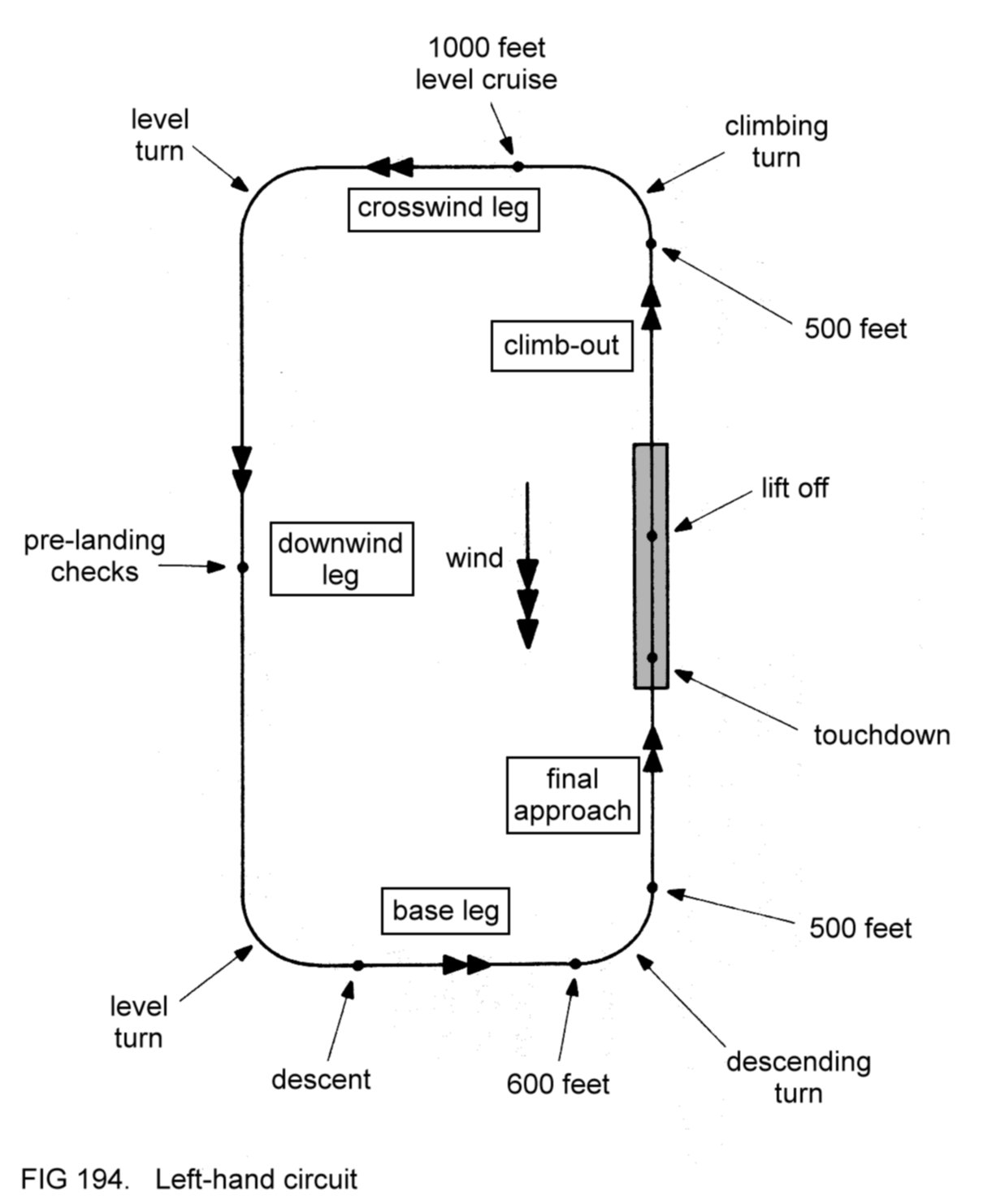
At most airfields the
circuit
height is 1000 feet above airfield level, as in the example shown.
Other airfields may have a circuit height of, for example, 800 feet.
Since
the take-off and landing are made facing into wind, two of the legs in
the circuit pattern are named accordingly. The term 'crosswind' is
self-explanatory; 'downwind' means opposite to the direction from which
the wind is blowing.
4.28 THE
TAKE-OFF
During the
take-off, the aircraft accelerates on the runway from a rest position
to a speed at which it can safely be made lo leave the ground and take
up a climbing flight path. In other words, the machine must be
accelerated to such a speed that an angle of attack safely below the
stalling angle will generate
the lift required to become airborne.
Of
course, the IAS corresponding to this take-off angle of attack depends
on the aircraft's loaded weight and on the flap position. The take-off
speed
quoted as an IAS in the Flight Manual refers to the
case when the aircraft is loaded to its MTWA with the flaps up. The
take-off speed
with the flaps at 'maximum lift' may also be given.
In practice, the
variation in take-off speed with weight is not significant, and
take-offs at lighter weights are made at the speed quoted for the MTWA.
If
the runway length required for take-off is well short of that
available, as is usually the case with light aircraft, take-off is
normally made with the flaps up, so that maximum rate of climb can be
attained as soon as the machine is airborne.
4.28.1
Normal take-off
technique (flaps up)
Having
completed his pre-take off checks, the pilot taxies his aircraft onto
the runway at the threshold and aligns the machine with the
centreline. This procedure is called 'lining up'. The pilot's view of
the runway will be as in Figure 195. (The lateral displacement of the
machine due to his offset seating is negligible.)

The brakes are released
and full power is applied. (The throttle should
be held fully open during the take-off.)
Any
tendency of the aircraft to deviate from the centreline is prevented
with the rudder pedals, which have their effect through the nosewheel
steering and also by virtue of the propwash flowing past the rudder. In
other words, directional control during the take-off run is merely a
matter of steering the aircraft along the centreline, as one would a
car. If the centreline is not marked, the pilot maintains equal
spacing from each runway edge.
Unless otherwise stated
in the Flight
Manual, the control wheel should be held centrally (with both ailerons
and elevators undisplaced) while the aircraft accelerates to take-off
speed.
The pilot will pay most
attention to the view ahead
during the take-off run to monitor the accuracy of his steering, with
occasional glances at the ASI. As the aircraft accelerates, he will
find that smaller rudder pedal movements will be needed to correct
displacements, because of the increasing effectiveness of the rudder.
When
the take-off speed has been reached, the control wheel is moved
rearwards until the nose of the aircraft begins to rise. The machine
will then become airborne, or lift
off. Slight
forward movement of the
control wheel will prevent the nose rising further, so that the IAS
will continue to increase (Figure 196).

When the aircraft has
accelerated to the maximum rate climbing speed,
the nose should be raised to the climbing attitude, so that this speed
is maintained.
During
the climb-out, the ailerons are used as necessary to keep the wings
level and the rudder to balance the aircraft. Figure 197 shows the
take-off profile.

At a safe height, the
engine power can
be reduced to climb power (if continuous use of full power is not
permitted) and the attitude lowered correspondingly to maintain the
correct IAS.
4.28.1.1
Wind
The main advantages to
be gained from taking off from a runway facing
into wind are:
(a)
the aircraft reaches its take-off speed at a lower groundspeed (GS),
so reducing both the stresses on the landing gear during the take-off
run and also the length of runway required to become airborne;
(b)
at any particular climbing IAS the subsequent gradient of climb
is
steepened, because of the reduced GS, and so any obstacles below the
flight path are overflown with greater clearance (Figure 198).

The stronger the wind,
the greater are these two effects.
4.28.2
Crosswind take-off
Frequently,
the wind blows from a direction which does not coincide exactly with
the available runway directions. When this is the case, the pilot is
obliged to make a crosswind
take-off.
An example of such a situation is
shown in Figure 199.
During the take-off run,
the directional
stability imparted by the fin will attempt to yaw the nose of the
aircraft into the wind, to nullify the asymmetry of airflow. This
weathercocking
action will tend to steer the machine away from the
centreline (Figure 200).
However, the crosswind
will also tend to blow the entire machine away
from the centreline in the opposite direction to the weathercocking
action (Figure 201).

The
two effects thus act in opposition to each other, although one may
predominate, depending on the aircraft's design. So far as the pilot
is concerned, however, the rudder pedals are merely used as necessary
to steer the machine along the centreline.
The asymmetric
airflow will also attempt to lift the 'into wind' wing prematurely,
because of the aircraft's laterally stabilising design features
(dihedral or high-wing arrangement). In the example shown, with a
crosswind from the left, the tendency of the left wing to lift during
the take-off run can be prevented by holding the control wheel
partially to the left, so that the displaced ailerons oppose the
wing-lifting effect. (Of course, the control wheel should be held
partially to the right if the crosswind is from the
right.)
As
is explained below, the lift off should be delayed until the IAS is a
few knots higher than the normal take-off speed. Immediately prior to
moving the control wheel rearwards, the ailerons should be centralised
again, so that the aircraft becomes airborne with its wings level.
Once
airborne, the machine will be blown away from the centre-line by the
crosswind (Figure 202). Note that this drifting effect is relative to
the
ground. The
airflow past the aircraft is symmetrical,
assuming that the
flight is balanced.

The drifting should be
allowed for by
turning the aircraft onto a heading slightly into wind, so that its
path over the ground, or track,
is along the extended centre-line
(Figure 203).
Note that if the
aircraft momentarily touches the
runway again after becoming airborne (perhaps because of unevenness of
the surface), the drifting effect will impose a sideways-acting stress
on the landing gear and tyres. By lifting off at a slightly higher
speed, the machine will leave the ground more crisply, so avoiding any
tendency to touch again.
4.28.2.1
Crosswind
component
In
Figure
199, the wind
can be
considered as being split into a headwind
component
(opposite to the runway direction) and a crosswind
component
(at right angles to the runway), as shown in Figure 204.

The
magnitude of the crosswind component depends on the strength of the
wind and the angle between the runway direction and the wind direction
(that is, the direction from
which the
wind is blowing). An increase in
either factor will increase the crosswind component.
To avoid
difficulty in controlling the aircraft during take-off, the pilot must
ensure that the crosswind component is not greater than the maximum
permitted for his aircraft (as specified in its Flight Manual).
Consultation of a crosswind table, such as that shown in Figure
205,
will enable him to assess the crosswind component. Of course, the table
is equally valid for a crosswind from the right. Note that wind
strength is expressed in knots.
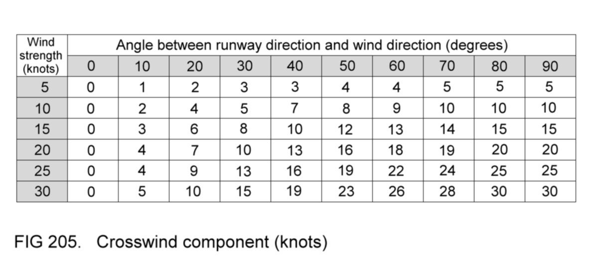
4.28.3
Short take-off
The
length of take-off run required to become airborne can be reduced by
use of the short
take-off
technique, which differs from the normal
technique in two respects:
(a) the flaps are set to
'maximum lift' (during the pre-take-off
checks);
(b) a lower take-off
speed (usually specified in the Flight Manual) is
used.
Once
airborne, the aircraft is made to fly at the optimum IAS for climbing
with the flaps at 'maximum lift'. When a safe height has been reached,
the flaps may be raised and maximum rate climb established.
Most
pilots use the short take-off technique when taking off from grass
runways, because not only does the grass retard acceleration slightly,
but also the surface is often more uneven than that of hard runways.
The reduced take-off run and lower take-off speed therefore help to
minimise the stresses imposed on the landing gear.
Note that a
further small reduction in take-off run can be gained by adopting the
following procedure at the start of the take-off:
(a) when the aircraft
has been positioned at the threshold, firmly
apply the brakes;
(b) set maximum power;
(c) release the brakes
and continue with the take-off as already
described.
4.28.4
Obstacle clearance
after take-off
At
some airfields, there are obstacles (such as trees) quite close to the
ends of the runways. The pilot will want to make certain that his
aircraft safely clears such obstacles after take-off. Maximum obstacle
clearance would be assured by:
(a) becoming airborne in
the shortest distance possible;
(b) thereafter achieving
the maximum possible gradient of climb.
Straight
away, we can see that a dilemma confronts us, for use of the flaps to
shorten the take-off run will detract from the subsequent climb
gradient. Conversely, take-off with the flaps up, whilst maximising the
climb gradient, will lengthen the
take-off run. Figure 206 illustrates the two cases.

The
Flight Manual will usually state the recommended obstacle clearance
technique for any particular design. The performance capabilities of
most light aircraft are such that use of the short take-off
technique, with the flaps at 'maximum lift', is more likely to give
better clearance over obstacles close to the runway. Of course, such a
choice is not available to the pilot of an aircraft not fitted with
flaps.
4.28.5
Rejected take-off
If, during the take-off
run, the pilot becomes unhappy about the
proceedings, the take-off should be rejected, by:
(a) closing the throttle;
(b) braking the aircraft
to taxying speed;
(c) steering clear of
the runway as soon as practicable to permit its
use by other traffic.
If
the take-off is rejected at high speed, for example just before lift
off, it may be necessary to apply maximum braking to avoid overrunning
the runway. In fact, if the latter is not very long, overrunning may be
unavoidable. The implications of this situation will be discussed later.
Reasons for rejecting
take-off might include:
(a) loss of power or
rough-running of the engine;
(b) poor acceleration;
(c) malfunction of the
ASI;
(d) if it becomes
evident to the pilot that insufficient runway remains
available for take-off speed to be reached.
Note
that situation (d) should not arise if the pilot has correctly assessed
the runway length beforehand as being adequate for his aircraft in the
circumstances prevailing.
4.29 FLYING
THE CIRCUIT
The aircraft is flown
around the circuit pattern as detailed in Figure 194. The following points
are noteworthy:
(a) the climbing turn
onto the crosswind leg is initiated as soon as a
height of 500 feet has been attained;
(b) loss of climb
performance during the turn is minimised by
restricting the bank angle to 15°;
(c)
in order to maintain the rectangular track, the pilot will need to take
up headings slightly into wind to allow for drift whilst flying the
crosswind leg and the base leg (Figure 207);

If a crosswind
prevails, similar compensation will be required during climb-out, on
the downwind leg and on final approach. Figure 208 illustrates the case
of a crosswind from the right;

(d) the pilot judges the
accuracy of
his track-keeping by reference to the aspect which the runway presents
throughout the procedure. Accuracy will improve with practice and
experience. As a general rule, the downwind leg is spaced about ½
nautical mile from the runway;
(e) the pre-landing
checks ensure
that the aircraft's controls are correctly set for landing. Typically,
they include the following:
(1) brakes off;
(2) harness tight;
(3) mixture rich;
(4) carburettor free of
ice;
(5) fuel cock selected
to draw fuel from a tank with sufficient
quantity;
(6) electrically-driven
fuel pump switched on.
The pre-landing checks
will also prepare the aircraft for a go-around
(refer back to 4.23.6)
should
one be made.
4.30 THE
APPROACH
An aircraft is
considered to be 'making an approach' after it has
started
its descent on base leg. The powered approach
involves the rather complex transition from level cruising flight with
flaps up to descending flight at approach speed with flaps lowered.
To divide the resulting
trim change and drag increase into more manageable quantities, it is
usual practice to lower the flaps in stages, setting them to 'maximum
lift' on base leg and then fully down on final approach.
Once the
approach is initiated, the pilot makes adjustments of power as
necessary to control the aircraft's rate of
descent,
whilst
maintaining the correct
approach speed
by appropriate changes of
attitude.
Ideally, the pilot should attempt to achieve a steady rate of
descent, with the engine at low intermediate power setting, so that the
aircraft finally reaches the runway threshold at ground level.
4.30.1
Base leg
From level cruising
flight, the approach is initiated on base leg as
follows:
(a)
reduce power to a low intermediate setting, whilst maintaining the
cruise attitude (which will assist the resulting deceleration);
(b) when the IAS has
fallen below the flap limiting speed, lower the
flaps to 'maximum lift', still maintaining attitude;
(c) as the IAS falls
further to the intermediate
approach speed,
lower the
nose as necessary to maintain this speed. The intermediate approach
speed is usually a few knots greater than final
approach speed;
(d) trim the aircraft.
A
rate of descent should be chosen such that the aircraft is ready to be
turned onto final approach at about 600 feet. On base leg, the oblique
appearance of the runway will gradually decrease as the machine
approaches the extended centre-line. Figure 209 shows the change in
appearance of the runway as base leg is flown in a left-hand circuit.

The
descending turn onto final approach should be anticipated, so that the
aircraft is positioned on the extended centreline at the completion
of the turn. Thus, in a left-hand circuit, the turn might be initiated
when the runway appears as in the centre example of
Figure 209.
4.30.2
Final approach
During the descending
turn
from base leg onto final approach, the pilot should carefully monitor
his ASI, lowering the pitch attitude as necessary to maintain the
correct intermediate approach speed. Here is a situation in which
poorly handled
controls, at too low an IAS, might well precipitate an inadvertent
stall. To minimise the increase in stalling speed during the turn, the
bank angle should be limited to 30°.
If the base leg descent
and
final turn have been well-judged, the aircraft will have completed the
turn at about 500 feet and will now be aligned with the runway's
extended centreline. The flaps should be fully lowered and the power
and attitude adjusted as necessary to achieve a steady descent path
towards the threshold at final approach speed. This speed for most
aircraft designs is slightly
less than the normal (minimum gradient) gliding speed, and will be
quoted as an IAS in the Flight Manual. Figure 210 shows a
typical view
from the windscreen on final approach.
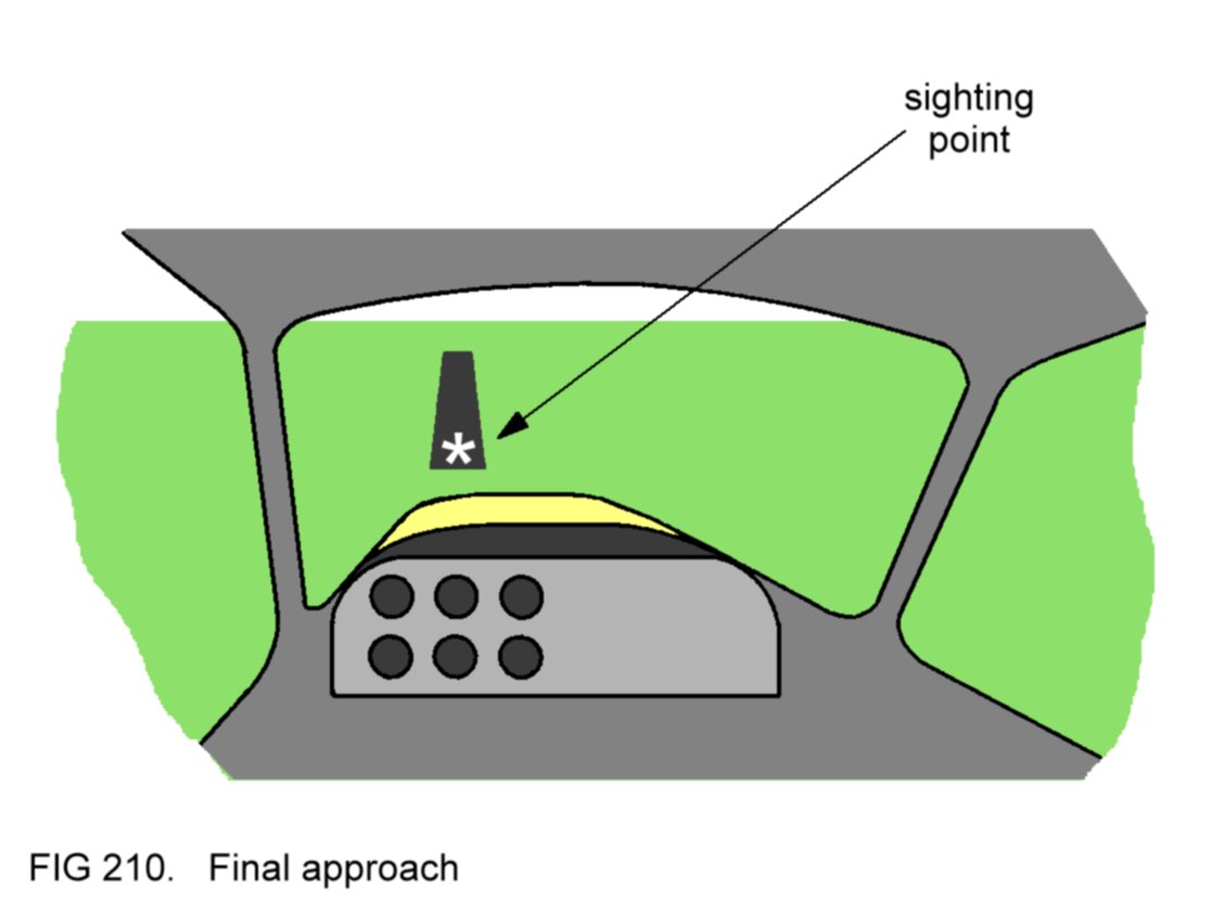
If the circuit pattern
has been flown correctly, a gradient of descent
on final approach of about 5° will bring the aircraft to the threshold
at ground level
(Figure 211).
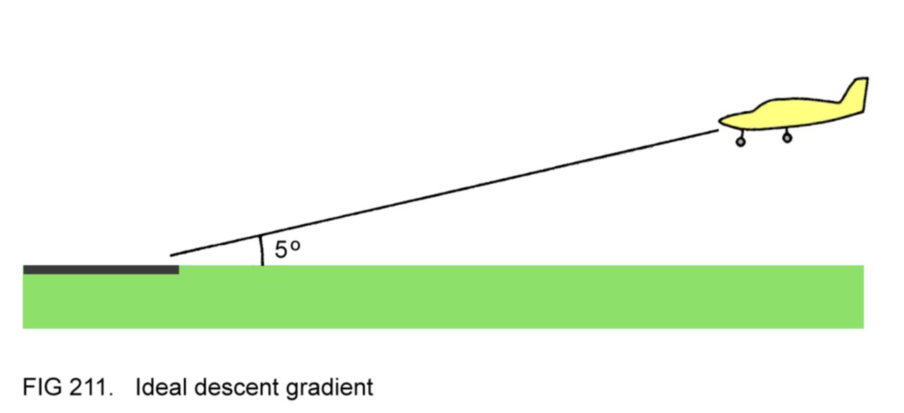
So
far as the pilot is concerned, the gradient of descent actually
achieved depends on two factors, namely the groundspeed (GS) and the
rate of descent.
Of course, GS itself will depend on the strength of the wind. Thus a
lower rate of descent will be required when a strong wind results in a
reduced GS, and a greater rate of descent when the wind is not so
strong. In other words, the pilot will find that the stronger
the wind,
the higher will be the power setting needed to achieve the ideal
descent gradient at the correct IAS.
4.30.2.1
Approach path
control
Of
course, the pilot cannot see a side view of his approach path. The only
clue as to whether the flight path is satisfactory is the view ahead
through the windscreen.
On any particular
approach path, the
position on the ground at which the aircraft will reach ground level
will appear to take up a fixed point in the windscreen. This 'sighting
point' serves as a reference for assessing the flight path. Figure 210
represents an ideal approach path, with the sighting point (shown as a
white asterisk in the diagram) coincident with the threshold.
If the
approach is too high,
the threshold will appear to be moving below the
sighting point, and the perspective of the runway and its surroundings
will appear too 'deep'. The consequence of too high an approach is that
the aircraft will reach ground level well past the threshold, as the
sighting point indicates (Figure 212).

On the other hand, if
the
approach is too low,
the threshold will appear to be moving above the
sighting point and the perspective of the runway and its surroundings
will appear 'flattened'. The consequence of too low an approach is that
the aircraft will reach ground level well short of the threshold,
again as the sighting point indicates (Figure 213).
A too-high
approach is corrected with a temporary increase in rate of descent, by
reducing power. During this corrective manoeuvre the lowered attitude
required to maintain approach speed will result in the threshold
appearing to move above the sighting point. The top image in Figure 214
represents a side
view.

Conversely, a too-low
approach is corrected by a temporary
reduction in rate of descent (increase in power). During
the
corrective manoeuvre the threshold will appear to move below the
sighting point. The bottom image in Figure 214 shows the side view.
In either case, the
corrective action should be continued until the runway perspective
changes to that associated with the ideal approach path. At this point
the original rate of descent should be restored, so that the sighting
point is now coincident with the threshold.
In conclusion, an ideal
approach path is one in which the sighting point coincides with the
threshold and in which the runway perspective is neither too 'deep' nor
too 'flattened'. Deviations are corrected by suitable adjustments in
power.
With practice and
experience, the pilot will come to
recognise such deviations in their early stages, and will therefore
need only small power adjustments to rectify the situation.
4.30.2.2
Centre-line
tracking
The
reader will appreciate that the pilot's workload during final approach
is considerable, because not only must he maintain the ideal approach
path, whilst monitoring his ASI, but also the aircraft must be flown
so that it tracks along the extended centreline.
Displacements from
the centreline are indicated by the associated oblique appearance of
the runway. They are rectified by turning onto a corrective heading
until the centreline has been regained, at which point the aircraft
is turned back onto the heading needed to track along the centreline.
Figure 215 shows a plan view of corrective action needed to
rectify a displacement to the right, with the pilot's forward view as
the correction is initiated.

If displacements are
detected in their
early stages, then only small heading corrections will be needed to
rectify the situation.
4.30.2.3
Alternative
technique for final approach
Some pilots favour a
different control technique for final approach.
They adjust the vertical path using pitch attitude and speed using
engine power setting. The rationale behind this technique is that the
approach is a defined
flight path
(in the same way as constant altitude is a
defined flight path in level flight, in which speed is also controlled
by engine power setting).
Whichever technique is
adopted, the aim is identical: to find the
combination of attitude and power setting that brings the aircraft
towards the runway threshold on the correct approach path at the
correct final approach speed.
4.31 THE
LANDING
The landing is a
manoeuvre in which the aircraft is brought into contact with the
runway and then decelerated to taxying speed. The primary
considerations are, firstly, that the machine is landed in such a way
that it will not become airborne again after touchdown, and secondly,
that the landing gear is not subjected to excessive stresses.
4.31.1 Normal
landing
technique
For
the typical light aircraft, the transition from powered approach to
landing begins at about 200 metres from the threshold, and involves a
change in the manner in which the controls are used.
The most
important change is in the role of the elevators, which, rather than
being used to control IAS (through attitude changes) as during the
powered approach, now take on the function of controlling the
aircraft's vertical flight path. This is because the landing manoeuvre
involves a change from descending flight to level flight just above the
runway. (The landing manoeuvre can therefore be considered as a
defined flight path).
The first phase of the
landing technique concerns the flight
path from the transition point to the threshold, during which the
power is gradually reduced to minimum. At the same time, the attitude
is raised at such a rate, and to such an extent, that the aircraft
arrives at the threshold in level flight just above the runway.
The
reader will appreciate that the reduction of power during the
transition, together with the raising of the nose, will result in the
reduction of IAS. If the transition point has been chosen at the
correct distance from the threshold, the aircraft will have
decelerated to threshold
speed
(specified as an IAS in the Flight
Manual) as it arrives at the threshold.
Figure 216 shows a side
view of the first phase of the landing
technique,
called the 'flare', together with what might be a typical view from the
windscreen just before the transition point, and as the threshold is
reached.

The second phase, called
the 'hold off', involves prolonging
the level flight path, offsetting the decaying IAS with increasing
angle of attack, until the latter is just below the stalling angle, at
which point the aircraft is allowed to touch down. The technique of
delaying ground contact until this landing angle of attack has been
reached results in touchdown occurring at a low speed, so reducing the
stresses imposed on the landing gear. The aircraft will contact the
ground on its mainwheels because of the high attitude needed to achieve
the high angle of attack in the final stages of the hold off.
Figure 217 illustrates the situation immediately prior to touchdown,
with the aircraft in the landing attitude.

After touchdown, the
nose is lowered until the nosewheel contacts the runway. In this way
the angle of attack of the wings, and hence the generated lift, is
reduced, and so the aircraft will remain firmly on the ground. The
brakes are now applied to decelerate the aircraft to taxying speed, so
that the machine can be steered off the runway as soon as practicable.
It will be appreciated
that use of the technique just described
achieves both objectives stated in 4.31.
Throughout the landing
manoeuvre the pilot's attention will be wholly
concerned with the view ahead. During the flare and hold off he will be
constantly assessing both the height of the aircraft above the ground
and also its attitude.
4.31.1.1
Control wheel
movement
Both the flare and hold
off involve rearward movement of the control
wheel. (Since the aircraft will have been trimmed in the approach
attitude, back pressure will be needed on the control wheel.) More
specifically, the rearward movement during the flare is interrupted as
level flight is achieved just above the runway. Then, in the hold off,
a more gentle movement is required, at a sufficient rate to prevent
premature touchdown, but without the aircraft gaining height; a
progressively higher attitude will be needed as the speed decays. When
the landing attitude, shown in Figure 217, has been attained, the
rearward movement of the control wheel is arrested, so that the
aircraft then sinks to the runway, contacting the ground on its
mainwheels. The control wheel is then gently moved forward to lower the
nosewheel on to the runway.
If, at any stage during
the flare or hold off, the control wheel is
moved rearwards too quickly, the aircraft will start to gain height.
This error is called 'ballooning' and is potentially dangerous because,
if not corrected, it may precipitate a stall, with the aircraft
dropping to the ground heavily. The error is rectified by a slight
forward movement of the control wheel. Then, as the aircraft nears the
ground again, the rearward control wheel movement is resumed. (In
practice, this corrective action is merely a temporary relaxation of
the back pressure needed on the control wheel to raise the nose.)
Figure 218 illustrates ballooning and its correction.

Conversely, if the
control wheel movement is too slow, the aircraft
will strike the ground prematurely at high speed. Besides subjecting
the landing gear, especially the nosewheel, to excessive strain, this
error is likely to result in the aircraft bouncing back into the air
again. Such a bounce, if it occurs, should be corrected as for
ballooning.
With practice and
experience, the pilot will be able to coordinate his
control wheel movement so that the ideal landing technique is achieved.
4.31.1.2
Centreline
tracking
As the ground is
approached during the flare, it is no longer
practicable to bank the aircraft, since the lower mainwheel will
contact the ground prematurely. Indeed, excessive bank may result in a
wing tip striking the ground.
If centreline
displacements occur, then, the rudder must be used
to
make corrections, while the wings are held level with the ailerons. In
fact, the pilot reverts to the technique used for take-off. In other
words, the rudder is used to steer the aircraft along the centreline
during the flare, the hold off and the subsequent landing run along the
runway after touchdown. In the latter case, the nosewheel steering will
assist the pilot in preventing displacements.
4.31.1.3
Wind
By landing on a runway
facing into wind, the aircraft touches down at
a lower GS, so reducing both the stresses imposed on the landing gear
and also the length of runway required to land and decelerate to
taxying speed.
4.31.2
Crosswind landing
If the wind direction
does not coincide exactly with the available
runway directions, the pilot will be obliged to make a crosswind
landing.
There are two methods available to accomplish
this manoeuvre.
In the first method the
pilot counteracts the sideways drifting effect
of the crosswind on final approach by adopting a heading slightly 'into
wind', so that the aircraft tracks along the extended runway
centreline (as in Figure 208).
This is called the 'crab' method, the
name reflecting the apparent sideways movement of the aircraft
relative to the ground, although it should be remembered that the
airflow past the machine is symmetrical, assuming that the
flight is
balanced.
In the second method the
pilot sets up a deliberate sideslip so that
the aircraft's fuselage is aligned with the runway centreline. For
obvious reasons this is called the 'crossed controls' method, and the
airflow past the aircraft is not symmetrical.
4.31.2.1
Crab method for
crosswind landings
Figure
208
illustrated the
case of a crosswind from the right. Figure 219 shows a corresponding
view through the windscreen on final
approach. Deviations from the centreline are corrected as already
described in 4.30.2.2.

The offset heading
should be maintained throughout final approach, and
during the flare and hold off. Again, the rudder is used to correct
centreline deviations once the flare has been initiated.
It will be appreciated
that if the aircraft is allowed to touch down
on this offset heading, the mainwheel tyres and landing gear legs will
be subjected to an undesirable sideways-acting force, because the
wheels will not be aligned with the machine's actual direction of
motion over the ground.
For this reason, the
offset heading should be maintained only until the
landing attitude has been reached, at which point the pilot should use
the rudder to yaw the aircraft's nose into line with the runway
direction, so that touchdown occurs with the machine actually heading
in this direction (Figure 220).

This use of rudder is
referred to as 'eliminating the drift'. Of
course, there will be a simultaneous tendency of the aircraft to roll
in the same direction as the application of rudder (refer back to
4.12.3.1), which must be
prevented by appropriate use of the ailerons,
so that the machine touches down with its wings level.
In the example
discussed, with a crosswind from the right, elimination
of the drift just prior to touchdown will require application of left
rudder; simultaneously, the control wheel should be moved to the right
sufficiently to hold the wings level. After touchdown, the pilot should
hold the control wheel in this displaced position to prevent any
tendency of the right wing to lift during the landing run, while using
rudder inputs as required to steer the aircraft along the centreline.
The controls would of
course be used in the opposite sense to cope with
a crosswind from the left.
A more serious error
than failing to eliminate the drift before
touchdown is that of doing so prematurely during the hold off, because
not only will the aircraft be drifting again when it does eventually
contact the ground, but it will also be blown away from the centreline
(Figure 221).

4.31.2.2
Crossed controls
(sideslip) method for crosswind landings
In our example of a
crosswind from the right the pilot applies right
bank and left rudder such that the fuselage is aligned with the
centreline throughout the approach. Effectively the aircraft's
resulting sideslip is exactly nullifying the drift, as shown in Figure
222.

The sideslip is
maintained throughout the flare and hold off so that
the aircraft eventually touches down firstly on its 'upwind'
mainwheel, in this example the right mainwheel. The machine is then
allowed to settle onto its 'downwind' mainwheel, followed by its
nosewheel, after which the controls are used as described for the
'crab' method during the landing run.
Some pilots combine the
two methods just described, starting final
approach using the 'crab' method but then switching to the 'crossed
controls' method as the aircraft approaches the transition point for
the flare.
4.31.3
Crosswind component
The pilot must not land
his aircraft in circumstances giving a
crosswind component greater than the maximum permitted for his aircraft.
4.31.4
Short landing
If it is necessary to
minimise the length
of runway required for landing and braking to taxying speed, the short
landing
technique is employed, in which the normal
approach path is
flown, but a lower threshold speed is aimed for. In this way, the
aircraft arrives at the threshold with its wings at the landing angle
of attack, so that touchdown occurs almost immediately, without a flare
or hold off.
Typically, the short
landing threshold speed is about 5
knots above the power-off stalling speed with flaps down. The reader
will appreciate that flight in this speed regime demands careful
handling of power and attitude if an inadvertent stall is to be avoided.
The
short landing technique commences on final approach, with the aircraft
initially established on the correct approach path at normal powered
final approach speed. The IAS is now reduced, in 5-knot stages, so that
the
aircraft arrives at the threshold at the short landing threshold speed
(specified in the Flight Manual as an IAS).
Each 5-knot reduction in
IAS involves the following sequence of actions:
(a) reduce power
slightly;
(b)
raise the nose to the attitude needed to decay the IAS to the new
target figure. (Action (a) is to prevent the aircraft momentarily
deviating above the correct approach path as the nose is raised);
(c) increase power again
to the setting necessary to continue along the
correct approach path at the lower IAS;
(d) trim the aircraft in
the new attitude.
Notice
that the controls are being used in the normal manner, with IAS
controlled by attitude, and rate of descent, and hence descent
gradient, by power setting.
At the threshold, a
brief increase in
power will check the descent, after which the throttle is closed and
the aircraft allowed to contact the runway without any further raising
of the nose. The nosewheel is immediately lowered onto the runway and
maximum braking applied (although the brake application should be
reduced if the mainwheels 'lock').
A point to bear in mind
is
that the attitude during the final stages of the short landing
approach is higher than for a normal approach (because of the higher
angle of attack of the wings) and the sighting point will probably be
below the windscreen. The pilot will have to assess the accuracy of his
approach path by reference to the ground adjacent to the threshold. If
the approach path is correct, the ground adjacent to the threshold will
appear to be level with the sighting point (Figure 223).

When flying
at these lower speeds, the pilot must avoid the use of very low power
settings, because of the ensuing reduction of margin above the stalling
speed and poorer effectiveness of the elevators.
4.32 GLIDE
APPROACH AND
LANDING
The
glide approach and landing is a manoeuvre which the conscientious pilot
practises regularly to sharpen his skill in bringing the aircraft
safely into land should engine failure occur.
The aim of the
practice glide approach is to arrive at the threshold at ground level
after initiating a glide from circuit height on base leg.
Relative
to the ground, the gradient of descent achieved during the glide
depends upon both the aircraft's GS and also its rate of descent. Thus
the wind strength will be an important factor to consider. Figure 224
shows an aircraft gliding at minimum gradient IAS both downwind and
upwind. Of course, the rate
of descent will be identical in both cases.
However, since in the upwind glide the aircraft's GS is less than in
the other, the gradient
of descent is steeper.

Although the pilot
will have a pretty good idea of the wind strength, he cannot guarantee
that it will remain constant throughout his glide. For this reason, he
will aim to arrange that the aircraft has a surplus of height during
the glide approach, until the final stages. The height surplus will
prevent failure to reach the threshold should the wind
turn out to be stronger than anticipated. Once sure of being able to
reach the threshold, the pilot can easily get rid of any residual
surplus height, whereas if it becomes apparent that the threshold will
not be reached, even when gliding at minimum gradient IAS, then there
is nothing that the pilot can do to retrieve the situation.
4.32.1
Glide approach
technique
The
circuit preceding the glide approach is as already described, except
that it is usual practice to shorten the downwind leg slightly, because
the aircraft's gradient of descent in the latter stages of the glide
approach will be steeper than for the normal powered approach (Figure
225).

The pilot maintains
cruising speed at circuit height on
base leg until the aircraft arrives at a point where he believes that
the threshold can be reached, with a surplus of height to spare,
without further use of power. He then fully closes the throttle and
initiates minimum gradient glide.
If it appears that the
surplus of
height is becoming excessive, there are three ways in which height can
be lost without departure from the minimum gradient gliding speed:
(a) by turning away
slightly from the airfield (Figure 226 top image);
(b) by lowering the
flaps;
(c) by sideslipping.

In
practice, method (a) is chosen since it enables methods (b) and (c) to
be held in reserve should more corrective action be needed at a later
stage in the approach.
Conversely, if the
height surplus seems to be disappearing, the pilot
can turn slightly towards
the airfield (Figure 226 bottom image).
Ideally,
the aircraft should be established on final approach not below 500
feet above airfield level, to give the pilot time to assess and, if
necessary, correct his flight path. If the base glide was
well-judged, the pilot will find that when he has turned onto final
approach, the sighting point will appear to be beyond the threshold,
indicating that the threshold will be reached with a surplus of height
to spare.
The flaps can now be set
to 'maximum lift'. (The attitude
should be lowered correspondingly to maintain speed.) The extra drag
will steepen the descent path, bringing the sighting point nearer to
the threshold.
When convinced that the
new flight path will still
enable the aircraft to reach the threshold with a surplus of height to
spare, the pilot can set the flaps fully down. (Another lowering of
attitude will be required to maintain speed.) The descent path
will be steepened again. If the flaps have been used correctly, the
sighting point will now coincide with the threshold.
Figure 227
shows a side view of the ideal final approach path, with the aircraft
eventually arriving at the threshold at ground level.

4.32.2
Mis-judged
approaches
Note
that the flaps should be used only when it is clearly apparent that the
threshold can be reached with a surplus of height to spare. For
example, if the pilot turns onto final approach only to find that the
sighting point coincides with the threshold, then it is obvious that
use of flaps will bring the aircraft down to ground level short of the
threshold. In this situation, it may be necessary to leave the flaps up
until just before the flare is initiated.
Taking this
consideration
one stage further, if the sighting point is short of the threshold
after the turn onto final approach, then it is
impossible to glide to
the threshold.
This situation is called 'undershooting'
(Figure 228).

It
should be borne in mind that any attempt to 'stretch the glide' when
undershooting by raising the aircraft's nose will only worsen the
situation by steepening the descent gradient (because the IAS
will drop below that for minimum gradient). The pilot should either
revert to a normal powered approach or initiate a go-around.
If,
having already lowered the flaps, it becomes clear that an undershoot
is developing, there is nothing to stop the pilot raising them again to
restore a shallower descent path.
At the other end of the
scale,
misjudgement may result in a situation where, even with the flaps down,
the aircraft will still have a surplus of height as it crosses the
threshold. Sideslipping (not permitted on some designs with flaps down)
will help to rectify the error, with the pilot reverting to balanced
flight just before the flare is initiated. On aircraft without flaps,
of course, sideslipping is the only method available for getting rid of
surplus height without change of gliding speed.
Assuming that the
runway is long enough, it is permissible to continue a mis-judged
practice glide approach through to the landing, even though the
aircraft may still be too high as it passes the threshold. If any
doubt exists about the adequacy of the runway length, however, a
go-around should be made.
4.32.3 The
flare
The flare should
be initiated at such a point that the aircraft decelerates to the
threshold speed specified for the glide approach as it arrives at
ground level. (For most light aircraft, this speed is 5 knots or so
higher than for the powered approach threshold speed to allow for the
increased
stalling speed during the flare with the engine at minimum power.)
Greater control wheel movement will be required than for the powered
approach because firstly, the approach path is steeper, necessitating a
greater pitch change to achieve level flight, and secondly, the
elevators will be less effective, because of the lack of propwash.
4.33 FLAPLESS
APPROACH
AND LANDING
If
for some reason the pilot finds that he is unable to lower the flaps
(perhaps because of failure of the activating mechanism) then he will
have to make a 'flapless' (in other words, flaps up) approach and
landing. The conscientious pilot will practise this manoeuvre
occasionally so that he is competent to deal with such a failure should
it occur.
Since the aircraft will
generate less drag on final
approach with flaps up, its descent gradient will be shallower than in
the flaps-down powered approach. For this reason, it is usual practice
to extend the downwind leg slightly in the preceding circuit (Figure
229).

The remainder of the
circuit is flown as already shown in Figure 194. With the reduced drag,
the pilot may find that,
even
having extended the circuit, less power will be needed to
achieve a steady descent path to the threshold than for the flaps-down
approach. To allow for the increased stalling speed, it is usual to fly
the flapless approach 5 knots or so above the normal flaps-down powered
approach speed. Again, power controls rate of descent and attitude
controls IAS.
On final approach it
will be found that a higher
attitude is required than for the flaps-down approach, because the
wings are at higher angle of attack, and the sighting point will appear
lower in the windscreen. Because of the shallower descent gradient the
runway aspect will also appear slightly 'flattened'. When the correct
approach path is being
followed, the sighting point will coincide with the threshold. Figure
230 illustrates.

Compare
the view through the windscreen in Figure 230 with that in Figure 210,
and refer back to Figure 174
to appreciate the reason for the different
sighting points.
4.33.1
The flare and
landing
The flapless
threshold speed is usually 5 knots or so above that for the flaps-down
powered approach, again to allow for the increased stalling speed.
Otherwise the flare and hold off are as already described in 4.31.1.
When the aircraft has attained the landing attitude, and hence the
landing angle of attack, it will be flying faster than if its flaps
were down, the higher speed matching the reduced lifting ability of the
wings. Thus touchdown will occur at this higher speed.
Furthermore,
the deceleration during the hold off will be slower, because of the
reduced drag. The two effects combine to increase the length of the
runway required to land and brake to taxying speed.
If a flapless
landing is made from a glide approach, it is usual to add a further
small increment to the threshold speed to allow for the increased
stalling speed during the flare with the engine at minimum power.
4.34 THE
GO-AROUND
The
go-around manoeuvre serves the vital function of enabling the pilot to
extricate himself from a poorly executed approach, when the procedure
described in 4.23.6 would
be
carried out. Of course, if a flapless
approach is being flown, the pilot can initiate maximum rate climb
straight away.
A go-around should also
be initiated if the pilot
flares prematurely, or balloons or bounces excessively, or otherwise
misjudges his landing. In this situation, the procedure is modified
slightly:
(a) apply full power;
(b) adjust attitude as
necessary to achieve level flight;
(c) when the IAS has
increased sufficiently, initiate a climb and
complete the procedure as already described.
Having
carried out a go-around, the pilot should reposition his aircraft in
the circuit pattern for a further attempt at approach and landing.
4.35
THE WINDSOCK
By now, the reader will
understand the importance of knowledge of wind
direction and strength when taking off or landing.
The
windsock is
a simple device enabling the pilot to assess the wind. It
consists of a cylindrical sleeve of fabric, usually coloured
yellow
or orange, mounted on a pole adjacent to the runway. Besides indicating
the wind direction, it is constructed in such a way that, the
stronger the wind, the more the windsock streams away from the
vertical. Figure 231 illustrates this.

4.36 STEEP
TURNS
In steep turns, the
aircraft is made to turn using angles of bank in
excess of 30°.
4.36.1
Lift increase
The
aerodynamic factors involved in medium turns also apply to steep turns,
differing only in degree. It has already been explained that it is
necessary to increase the lift generated by the wings in turning flight
relative to that required for straight flight. With increasing angle of
bank, the lift increase necessary to give the required vertical
component becomes considerable (Figure 232).

4.36.2
Rate of turn
Figure 232 shows that
the greater the angle of bank, the larger is the
sideways-acting force arising from the tilting of the lift force, and
so the greater is the rate of turn at any particular IAS.
By banking
steeply, high rates of turn are attainable. The practical value of
steep turns, then, is to enable the aircraft to change direction more
quickly than if medium angles of bank are employed.
4.36.3
Increase of
stalling speed
As
the angle of bank increases, so does the aircraft's stalling speed
(refer back to 4.24.4). At
steep bank angles the increase becomes
considerable. For an aircraft which has a stalling speed of 50 knots
IAS in straight flight, the stalling speed at various angles of bank is
as stated in Figure 233.

4.36.4
Steep level turns
It has been
seen that, in turning flight, the increased lift is generated by
increasing the angle of attack of the wings. In medium level turns,
the extra wing drag results in a slightly lower IAS, but the margin
above the stalling speed is still comfortably adequate.
As the angle
of bank is steepened, however, the IAS will decrease, and the stalling
speed will increase, until finally the two coincide, with the wings at
the stalling angle of attack. In other words, the aircraft will stall.
To
generate the increased lift at these steeper bank angles without
bringing the wings to the stalling angle of attack, it is therefore
necessary to prevent the IAS decay. In practice, extra power is used
to
counteract the increased wing drag. Not surprisingly, it will be found
that, the greater the chosen angle of bank, the greater will be the
power setting needed to maintain speed.
So far as maintaining
level
flight is concerned, the pilot will find that greater back pressure is
required on the control wheel to hold the correct pitch attitude,
compared to turns with shallower angles of bank.
In summary, the
steep level turn is entered as for the medium turn, except that power
is simultaneously increased sufficiently to maintain IAS.
During the
turn, elevators are used as necessary to maintain level flight,
ailerons to prevent any tendency of the bank angle to change, rudder to
balance the aircraft and power to control IAS.
Figure 234 shows
typical attitudes for level turns using 45° bank angles. Notice that
the
attitude in the turn to the right appears lower than in that to the
left, because the pilot's seating position is on the left-hand side of
the cabin.

Compared to the medium
turn, greater anticipation is
required when reverting to straight flight on a chosen heading. The
steep turn is completed as for the medium turn, except the power is
simultaneously reduced to the setting in use before the turn was
entered, so that the IAS remains constant.
4.36.4.1
Stall avoidance
The
reader will appreciate that in steep turns the aircraft is being flown
in an angle of attack regime close to the stalling angle, especially at
higher angles of bank.
Suppose that momentarily
the pilot
accidentally relaxes the back pressure on the control wheel. The nose
will drop and so the aircraft will being to descend. The pilot,
observing the descent from consultation of his flight instruments
(altimeter and VSI) will apply extra back pressure to try to raise the
nose back to the correct attitude for level flight. This action might
well precipitate a stall, with the nose failing to rise despite the
rearward movement of the control wheel.
The problem is overcome
by
reducing
the angle of
bank, and thus reducing the stalling speed, prior
to any attempt to raise the nose. As soon as level flight
has been
restored the bank can be increased again as desired.
If, during a
steep turn, the pilot becomes aware of pre-stall symptoms, such as
activation of the stall-warning device, forward movement of the control
wheel (in practice, relaxation of the back pressure) will lower the
angle of attack of the wings and so avert the stall. When satisfied
that he has full control of the aircraft, the pilot can then make a
further attempt to turn, either increasing power or reducing the angle
of bank to prevent recurrence of the incipient stall.
If the aircraft actually
stalls, as indicated by sudden dropping of the
nose,
recovery action should be taken without delay as described in 4.25.4.
(Note that a wing drop at the stall may either increase or decrease the
angle of bank.)
After taking the
precautions described in 4.25.5,
deliberate stalling in steep turns will enable the pilot to maintain
proficiency with the recovery action.
4.36.4.2
Recovery from
spiral dive
Failure
to apply sufficient back pressure on the control wheel to maintain
level flight in an attempted steep turn will probably result in a
spiral dive, with the aircraft descending and its IAS increasing.
This error is most likely to occur when high angles of bank are in use.
Recovery from the spiral
dive is as described in 4.25.10.
4.36.4.3
Maximum rate
turns
We
have seen that in a medium turn, it is unnecessary to increase power to
overcome the extra wing drag since only a small reduction in IAS is
involved. It has also been shown that if the bank angle is increased,
the IAS will decrease, and the stalling speed will increase, until the
two eventually coincide and the aircraft stalls. The angle of bank at
which the wings are just below the stalling angle of attack, then, is
the maximum sustainable in level flight at that particular power
setting.
If now the engine power
setting is increased, this angle of
bank can be sustained at higher IAS, in other words, with the wings at
lower angle of attack. Taking the argument one step further, at this
new power setting we can increase the angle of bank, without stall
occurrence, until a situation is again reached in which the extra drag
decelerates the aircraft to stalling speed, which will now be greater.
Thus
the
maximum angle of
bank sustainable in level flight depends on power
setting. To
clarify the point, Figure 235 illustrates the
case with
the engine at cruise power and at full power.
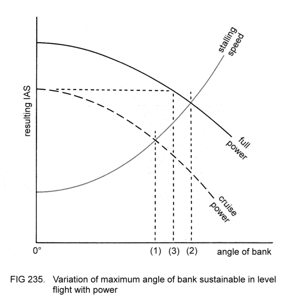
We can conclude that
angle of bank (1) is the maximum sustainable in level flight with the
engine at cruise power, and angle of bank (2) is that sustainable at
full power. In other words, sustained
level turns are impossible at
greater angles of bank, since no more power is available.
The
diagram also shows that cruising speed can be maintained by increasing
power up to angle of bank (3), when full power is needed. Greater
angles of bank will entail reduction of speed.
Since we know that
rate of turn depends upon angle of bank, it will be appreciated that
the
maximum achievable
rate of turn in level flight occurs at the
maximum sustainable angle of bank, with the engine at full power and
the wings just below the stalling angle.
In practice, maximum
rate
turns are flown by applying full power and increasing the bank angle,
simultaneously increasing the rearward movement of the control wheel
to maintain level flight, until the stall-warning device activates, or
until pre-stall buffeting is detected. This state of affairs is
maintained until it is desired to complete the turn. Considerable back
pressure will be required to hold the control wheel in the correct
position during the turn. If the aircraft stalls, recovery action
should be taken without delay. (The engine will already be at full
power, of course.)
Most pilots practise
maximum rate turns occasionally to sharpen their
coordination in the use of aircraft's controls.
4.36.5
Steep gliding turns
If
a steep turn were to be attempted whilst gliding at minimum gradient
IAS, it is quite likely that at this speed the wings would reach the
stalling angle. An increase in IAS is therefore required, and
the only method available to the pilot of doing so when gliding is by
the adoption of a lower
pitch attitude.
As a rule of thumb the
IAS
should be increased by 5 knots for every 10° bank (or fraction of 10°)
over 30°. Thus a 45° banked gliding turn should be flown at minimum
gradient speed plus 10 knots.
To attain these higher
speeds against
the opposing effect of the increased wing drag, quite steep nose-down
pitch attitudes will be necessary. With the nose so far below the
horizon, accuracy of speed control will require considerable skill and
practice. The increased drag will also result in steep decent
gradients, and hence high rates of descent, which the pilot should bear
in mind. Because of these factors, it is not usual practice to carry
out gliding turns at angles of bank in excess of 45°. Figure 236
demonstrates a typical attitude for a 45° banked gliding turn to the
left.

Steep angles of bank in
gliding flight might be required when
bringing the aircraft into land after engine failure. Pilots
therefore practise the manoeuvre occasionally to maintain competence.
4.37 REVIEW
OF CONTROL
FUNCTIONS
At this stage, it is
worth reviewing the functions of the aircraft's
most important controls in various phases of flight.
4.37.1
Function of
elevators
The
elevators are used to maintain or change the pitch attitude. The pitch
attitude is chosen to maintain either:
(a) a defined vertical
flight path, such as level flight or the landing
flare (and,
optionally, final approach);
(b) a desired IAS, such
as in climbing or descending flight.
4.37.2
Function of
ailerons
The
ailerons are used to select and hold any chosen angle of bank, and to
remove the bank when so desired. However, they should not be used to
attempt to rectify wing drop in a stall, nor during spin recovery.
4.37.3
Function of rudder
The
primary function of the rudder is to balance the aircraft's flight. In
specific phases of flight, it has different functions:
(a) to prevent
bank-induced yaw when deliberately side-slipping;
(b) to maintain
constancy of heading during stall recovery and so
prevent autorotation;
(c) to oppose yaw during
spin recovery;
(d) to steer the
aircraft during take-off and landing (flare, hold off
and landing run).
4.37.4
Function of power
When the pitch attitude
is controlling the vertical flight path, power
adjustments are used to control IAS. When climbing
at maximum rate or maximum gradient, the engine is set to climb power
(maximum if permitted). In descending flight, power is used to control
rate, and hence gradient, of descent.
4.37.5
Flight near
stalling regime
During
flight the pilot should aim to keep his IAS comfortably above the
stalling speed (and hence the angle of attack of the wings safely below
the stalling angle). However, deliberate flight near the stalling
regime is necessary:
(a) when stalling is
intentional;
(b) during the hold off
whilst landing;
(c) during the approach
for a short landing;
(d) in steep turns.
4.38
INSTRUMENT FLIGHT
Instrument
flight is a technique in which the pilot assesses the aircraft's
behaviour entirely by reference to the flight instruments. This
technique is used when poor visibility (such as when flying in cloud)
obscures the view of the outside world to the extent that the attitude
of the aircraft cannot be determined.
The discussion which
follows
is of a general nature, stressing the most important considerations
which apply to instrument flight. However, it is beyond the scope of
this book to make a detailed examination of all the factors involved.
4.38.1
Physiological
aspects
On
the ground, man's assessment of his orientation with regard to the
vertical derives from the brain's interpretation of information from
three sources:
(a) eyesight;
(b) the balance organs
in the ears;
(c) various nerves
throughout the body (for example, those in the feet
when standing up).
The
brain gives priority to visual information when this is available. If
vision is denied (as when in total darkness) the two secondary sources
supply sufficient information for the brain to assess the body's
orientation.
In flight, the nature of
the forces acting on the aircraft and its
pilot differ from
those experienced by the latter when he is groundborne. For this
reason, the brain's interpretation of information from the balance
organs and nerves may be erroneous.
Using the technique of
visual
flight, this shortcoming poses no problems, since sight of the outside
world is available and the brain naturally gives priority to this
information, which in any case is less likely to be misinterpreted.
If,
however, the pilot is denied sight of the outside world, as when flying
in cloud, then the secondary sources alone supply information, which
the brain is likely to misinterpret. For example, the pilot may gain
the impression that his wings are level when in reality the aircraft
is in a banked turn. Conversely, the situation may arise where the
wings are indeed level, but the pilot feels that the aircraft is in a
banked attitude.
It will be appreciated,
then, that it is impossible
for the pilot to control the aircraft unless he has information about
attitude which the brain will interpret correctly. We can see that the
two pre-requisites for correct assessment of the aircraft's attitude
are:
(a) reliable indications
of attitude;
(b) correct interpretation
of such indications by the brain.
When
the outside world cannot be seen, the first requirement is fulfilled
solely by the flight instruments. Interpretation of their indications
would present no problems, except that the brain has difficulty in
disregarding information from the balance organs and nerves. In other
words, the pilot may come to disbelieve the flight instruments because
he has the feeling
that the aircraft's attitude is different from that
indicated. The pilot
cannot hope to retain control of his aircraft
unless he accepts that the instrument indications are correct, and that
any sensations he may have which are at variance with these indications
must be disregarded.
Perhaps the most difficult aspect of
instrument
flight so far as the pilot is concerned is learning to believe the
instruments regardless of conflicting sensations that may be
experienced.
It is worth pointing out
here that for
a pilot who has
not been trained in instrument flight technique, the consequences of
entering cloud could be disastrous. Control of the aircraft will be
lost very quickly, because the pilot will instinctively react to his
sensations rather than to the flight instrument indications of the
aircraft's attitude.
4.38.2
Instrument scan
In view of the
foregoing remarks, it will be appreciated that a pilot flying in cloud
will need to devote nearly all of his attention to the flight
instruments. Specifically, the AI should be consulted most frequently,
perhaps every two seconds or so, so that the pilot has a continuous
idea of the aircraft's attitude.
In between such consultations, the
remaining instruments should be read, both to cross check the AI's
information and to assess the aircraft's performance. This
technique
is called 'scanning' the instruments (Figure 237).

Note that the aircraft's
pitch attitude is indicated directly by the AI
and
indirectly by the ASI, altimeter and VSI. Of course, accurate knowledge
of the engine power setting is also needed to infer pitch attitude from
these last three instruments. For example, a particular IAS implies a
higher attitude when the engine is at high power than when low power is
set. Thus the tachometer
will need to be referred to occasionally.
Bank
is indicated directly by the AI and indirectly by the DI and TBI (both
of which respond to the turning
effect arising from a banked attitude).
4.38.3
Control technique
So
far as use of the aircraft's controls is concerned, there is no
difference in technique between visual flight and instrument flight.
The AI replaces the earth's horizon for assessment of attitude.
If
the flight instruments show that the aircraft's behaviour differs from
that required, suitable alterations of power and attitude are made to
rectify the error. When making a power correction, the pilot will refer
to the tachometer, so that he can make an accurate assessment of the
power setting in use. Similarly, he will refer to the AI when adjusting
attitude. As in visual flight, power and attitude are set in a
combination which the pilot believes will give the desired behaviour.
If the results are not exactly as intended,
further adjustments
will be required. Having made corrective inputs, the pilot must wait
for the instrument indications to stabilise before applying further
corrections, allowing for the aircraft's inertia. He must avoid
'chasing the needles' - in other words, over-controlling. Care must
also be taken not to become over-attentive to one instrument at the
expense
of the others. The pilot must discipline himself to scan all the
instruments in a systematic manner, so that he has continuous knowledge
of the aircraft's overall behaviour.
The pilot's workload
during
instrument flight is greater than when visual flight technique is in
use. This is mainly because in the former case a conscious mental
effort is needed to interpret the aircraft's attitude from the
instrument indications, whereas in the latter the earth's natural
horizon is to be seen all around the aircraft, and attitude is
assessed subconsciously, so using less of the pilot's mental capacity.
Of course, there are also other demands on the pilot's attention, such
as monitoring the engine gauges and operating the carburettor heat
control periodically to ensure that the carburettor is free of ice.
4.38.4
Navigation
In
visual flight, navigation is mainly by reference to landmarks on the
ground, correlating such features to those marked on a navigational
chart. If the aircraft features GPS equipment, the GPS map display can
offer confirmation of geographic location and track (actual path over
the ground or sea).
When flying in cloud,
sight of the ground is not available to
the pilot, and GPS or alternative means must be used to determine the
aircraft's geographic location. Alternatives include:
(a) by interpretation of
information from ground-based radio
facilities;
(b) with the assistance
of ground-based personnel manning radio
equipment designed for this purpose.
Method
(a) requires the aircraft to be fitted with appropriate navigational
radio
equipment and the pilot to be knowledgeable in the use of such
equipment and in interpretation of the information derived from it.
Method
(b) is the only choice available to pilots of aircraft equipped
solely with COM radio. Depending on their type of radio installation,
the ground personnel will be able to advise the pilot either of the
aircraft's direction, or bearing,
relative to the installation, or of
its actual position
(in terms of bearing and distance from a chosen
reference). The former type of radio installation is known as VDF (VHF
direction-finding equipment), and the latter as 'radar' (radio
detection and ranging).
4.38.5
Terrain clearance
Denied
sight of the ground, the pilot will have to ensure at all times that
his chosen altitude is safely above any terrain that the aircraft may
overfly. (Of course, knowledge of the elevation of such terrain will be
necessary.) Again, when descending in cloud, a flight path must be
chosen in which the pilot is positive that terrain will be safely
cleared. This requirement implies the necessity of knowing the
aircraft's exact position throughout the descent. One of the
navigation methods described in 4.38.4 will be needed.
Similar
considerations apply when approaching to land. Each such approach has
an associated decision
altitude,
down to which the pilot may safely fly
in cloud. At decision altitude, if the ground cannot be seen, the pilot
must make a go-around, following a previously specified flight path. He
then has the choice of either making another approach attempt (if he
believes that the weather conditions will be such that sight of the
ground will be regained by the time decision altitude is reached) or
flying to a location where better weather conditions are more
likely to
result in a successful approach. Having regained visual contact with
the ground, the pilot can position his aircraft for landing.
4.38.6
Collision avoidance
Flying
in cloud, a pilot will not be able to see conflicting traffic, because
not only is the visibility from the cabin severely restricted
(effectively the aircraft will be in fog), but the pilot's attention
will be devoted mainly to the flight instruments.
To prevent
collisions between aircraft flying in cloud, their pilots are obliged
to conduct their flights in accordance with a special set of
regulations, called Instrument Flight Rules (IFR), whose purpose is
to ensure adequate separation between such traffic. A detailed
description of IFR is beyond the scope of this book;
suffice it
to say that their purpose is achieved by imposition of certain
restrictions
on aircraft flying in weather conditions which are unsuitable for
visual flight. In addition, traffic separation can be positively
implemented with the assistance of ground-based personnel equipped
with radar, which enables them to determine the positions of all
aircraft in the vicinity of the installation.
A recent development in
avionics is equipment
showing nearby aerial traffic on aircraft GPS map displays. Besides
relative position, this equipment shows relative altitude of the
traffic so that pilots may assess the three-dimensional separation of
their aircraft from this traffic. The equipment requires aircraft to be
fitted with transponders (see 2.8.1)
incorporating the appropriate
avionics. This equipment will, of course, also be beneficial to pilots
operating under visual conditions, supplementing their lookout.
4.38.7
Meteorological
aspects
Cloud
consists of minute particles of water, which have no detrimental
effect on fight unless the air temperature is at or below freezing
(0°C). An aircraft flying through cloud in the latter conditions is
likely to accumulate ice on the forward facing areas of its airframe as
it meets these particles. The dangers of ice accumulation on
aircraft are significant but their description is beyond the scope of
this book.
4.39
CONSTANT-SPEED
PROPELLERS
In
3.10.4.1 it was explained
that a fixed-pitch propeller cannot function
efficiently in all phases of flight, and that for small aircraft
designs it is usual to fit a propeller whose blade angle gives optimum
efficiency in cruising flight.
For larger aircraft, the
impaired performance resulting from propeller inefficiency during
particular phases of flight is unacceptable. Such machines require a
propeller whose blades can be turned to a lower angle (fine pitch) for
use at high engine power settings and low forward speed, for example
during take-off and climb, and then turned to a higher angle (coarse
pitch) for
cruising flight. In other words, a
variable-pitch
propeller
is required (Figure 238).

Ideally, the pilot
should be able to
adjust the pitch so that the propeller blades always meet the airflow
at the most efficient angle of attack. However, there is no means by
which he can assess the blades' angle of attack; instead, a
constant-speed
governor
is fitted to control the pitch. The whole
assembly is now termed a constant-speed
propeller,
and is remotely
controlled by the pilot's propeller
control lever
(sometimes referred
to as the pitch lever).
The pilot uses the propeller control lever to
set the desired speed of rotation of the propeller (and therefore of
the engine) according to the phase of flight.
4.39.1
Theoretical
considerations
The
constant-speed governor compares the actual engine RPM with that
demanded by the setting of the propeller control lever. The governor
eradicates any discrepancy between the two by altering the pitch. Once
the desired RPM requirement has been set with the lever, any alteration
of circumstances which would tend to increase the RPM (for example,
opening of the throttle or increase of forward speed) is countered by
the governor, which coarsens the pitch (increases the blade angle). The
effect is to increase the angle of attack of the blades, and therefore
the torque, which retards the engine speed to the original RPM.
An opposite sequence of
events occurs if any alteration of
circumstances attempts to reduce the engine RPM.
Note
that the governor can adjust the pitch only within the mechanical
limits of the pitch-changing mechanism in the propeller hub, the limits
being termed the fine
pitch stop
(at the lowest blade angle) and the
coarse
pitch stop
(at the highest angle). For example, if the blades
are at the fine pitch stop, any reduction of engine RPM cannot be
countered - the behaviour will be the same as that of a fixed-pitch
propeller.
4.39.2
Technical
description
The pitch-changing
mechanism forms part of the propeller hub assembly and is powered by a
special supply of oil from the engine's main oil system. Oil is piped
to the hub (from the hollow crankshaft) and its pressure is used to
activate the mechanism as directed by the setting of the propeller
control lever.
The propeller control
lever is sited adjacently to
the other engine controls in the cabin. Figure 239 shows a typical
arrangement. Notice that the control knobs have different shapes (and
usually different colours) to assist the pilot in their identification.

When
the propeller is acting in the constant-speed range (that is, with its
blades in between the fine pitch and coarse pitch stops), the pilot can
increase RPM by setting the lever to a more forward position and vice
versa. Thus maximum RPM are attained when the lever is fully forwards.
4.39.3
The manifold
pressure indicator
Opening
or closing the throttle will have no effect on engine RPM if the
propeller is acting in the constant-speed range. Hence, in addition to
the tachometer, aircraft featuring constant-speed propellers are
equipped with a manifold pressure indicator (MPI) for assessment of
engine power output. The MPI is mounted on the instrument panel
(usually next to the tachometer) and shows the pressure of the fuel-air
mixture in the inlet manifold. A typical presentation is illustrated in
Figure 240.

The MPI is usually
calibrated in inches of mercury (in
Hg), these being units of pressure. As the throttle is opened it allows
more mixture to enter the inlet manifold for combustion in the
cylinders, and so the reader will appreciate that a higher indication
on the MPI signifies a higher power output.
4.39.4
Operating technique
The
basic operating technique for constant-speed propellers is to set the
recommended manifold pressure setting (with the throttle lever) and
the engine RPM setting (with the propeller control lever) appropriate
to the phase of flight. These recommended settings are to be found in
the Flight Manual. Correct
use of the controls in this respect will
ensure that the propeller blades are working at or near their most
efficient angle of attack throughout the various phases of flight.
Departure
from the recommended settings will result in the propeller blades
working at other than the most efficient angle of attack. Usually, no
harm will be done, except in the case where low engine RPM are set with
the propeller control lever and high manifold pressure with the
throttle lever. The consequence of such action is to make it difficult
for the relatively slow-moving pistons to absorb the large pressure
increases in the cylinders during combustion of the mixture. Most
engines are not designed to withstand this misuse of the controls. (A
motoring analogy is putting one's foot
down on the accelerator pedal while the car is moving at low speed in
high gear.)
Note that, for any
particular manifold pressure setting,
selection of higher RPM results in increased power output from the
engine (and hence increased thrust from the propeller). Thus when
maximum power is required from the engine (as during take-off), the
pilot sets both throttle and propeller control levers fully forward.
For
an aircraft fitted with a fixed-pitch propeller, use of the mixture
control lever to lean out the mixture for cruising flight is as
explained in 4.2.2. Of course,
this procedure is unsuitable for an
engine driving a constant-speed propeller - the governor would merely
reduce the blade angle to maintain RPM until the blades were at the
fine pitch stop, by which stage the mixture would be over-lean and the
power output from the engine would be considerably reduced.
As
the mixture is leaned out, the rate at which fuel is consumed by the
engine is reduced. At the same time, the temperature of combustion in
the cylinders (and hence the temperature of the exhaust gases)
increases, because there is no surplus fuel to cool the mixture. A
gauge which measures rate of fuel consumption can therefore be used for
calibration of mixture strength, as can one which indicates exhaust gas
temperature (EGT). The former is often referred to as a fuel flow meter.
An aircraft fitted with
a constant-speed propeller will most likely
feature either a fuel flow meter or an EGT gauge, or both, on its
instrument panel. The procedure for leaning out the mixture is then as
follows:
(a) use the throttle
lever to set recommended manifold pressure;
(b) use the propeller
control lever to set recommended RPM;
(c) move the mixture
control lever backwards to achieve the recommended
indication on the fuel flow meter or EGT gauge.
In some aero-engines
fitted with FADEC systems (see 2.2.18)
the FADEC computers also control propeller pitch to ensure
optimum operational efficiency in all phases of flight. In aircraft so
equipped there will be no need for the propeller control lever.
4.40
RETRACTABLE LANDING
GEAR
A
retractable landing gear is raised as soon as the aircraft is safely
airborne on take-off (after a brief application of brakes to stop the
mainwheels spinning). Lowering the landing gear prior to landing
usually features as one of the items in the pre-landing checks.
Indicator
lights on the instrument panel show the position of the landing gear
legs, enabling the pilot to confirm that the three legs do indeed lock
themselves in the position demanded by the selector.
The Flight
Manual will probably specify the maximum permitted IAS for retraction
and for lowering of the landing gear (the two speeds may differ). The
pilot should not violate such limiting speeds, otherwise damage might
be caused to the retraction mechanism or landing gear doors by the
airflow.
When descending,
lowering the landing gear also serves as a
useful means of steepening the gradient (by increasing drag) if so
desired.
5 EMERGENCY HANDLING
Serious emergency
situations are uncommon in aviation, because of
the careful regulation of flight procedures and the high standard of
reliability of aircraft and aviation ground equipment.
Nevertheless,
the pilot must be able to cope competently with such a situation should
it arise, primarily to safeguard the lives of his passengers and
himself. A satisfactory degree of competence in dealing with
emergencies can only be assured by appreciation of the various factors
involved and by frequent practice of the relevant procedures; in this
way the pilot will not be caught unawares should unforeseen
difficulties occur.
It is worth noting that
there is usually
sufficient time to take stock of the situation and plan a suitable
course of action. Furthermore, the familiarity with emergency
procedures gained by frequent practice will assist the pilot in making
sensible decisions promptly, and will minimise the erosion of judgement
that naturally occurs when anxiety besets the pilot.
An important
consideration in dealing with emergency situations is
sensible prioritisation of tasks. Retaining control of the aircraft and
ensuring it is following a safe flight path at a safe speed is the
first priority, followed by the appropriate actions or checklist(s).
A review of navigational factors may be required - can the
aircraft continue along the original intended route or are changes
necessary? In the
following discussions, reference is occasionally made to transmission
of distress calls on the radio to alert ground personnel to the
emergency situation and thereby obtain their assistance or advice. Such
radio calls should not be made before the more essential actions have
been completed.
A useful mantra
summarising prioritisation is : aviate,
navigate, communicate.
5.1 ENGINE
FAILURE
Modern
aero-engines are extremely reliable, and malfunctions are more likely
to occur as a result of pilot mismanagement than because of actual
mechanical failure. Bearing this in mind, the pilot should take the
following precautions before and during every flight:
(a) ensure that
sufficient fuel and oil are carried for the intended
flight, with adequate reserves;
(b)
monitor the fuel quantity gauges frequently and ensure that no tank is
allowed to run dry while it is supplying fuel to the engine;
(c) monitor the engine
gauges frequently and terminate the flight as
soon as possible if abnormal indications are shown;
(d) operate the
carburettor heat control periodically to ensure that
the carburettor remains free from ice;
(e) avoid mis-setting of
the mixture control.
For
reasons which will soon become clear, other factors which should be
borne in mind throughout any flight are the wind direction (relative to
the aircraft's heading) and the elevation of the terrain over which
the aircraft is flying.
Should total engine
failure occur, the aircraft will not be able to
maintain height, and the pilot will be
obliged to glide down and make a forced
landing. If
the aircraft were
within comfortable gliding range of an airfield, the pilot would
obviously choose to land there. However, it is more likely that the
machine will not be able to reach the nearest airfield, in which case
the pilot must select the best field within comfortable gliding range
for the forced landing.
If the failure is only
partial, it might
be possible for the pilot to reach the nearest airfield, using
whatever power is available from the engine and flying the aircraft at
its minimum gradient gliding IAS to achieve the shallowest possible
descent path. However, it should be borne in mind that a partial
failure might develop into a total failure. It would be unwise, then,
to attempt to reach an airfield if flight over terrain unsuitable for
a forced landing were involved. In this case, the safest course of
action would be to close the throttle and initiate the forced landing
procedure as for total failure, remembering that the residual power
available from the engine can be used should it be needed to reduce
rate of height loss. The pilot should not rely on this residual power,
however, since it will not be available if the failure becomes total.
If
the failure is accompanied by severe vibration, signifying mechanical
defect, the engine should be shut down immediately to prevent it from
being wrenched from its mountings.
If the cause of the
failure
is not known, then after commencing the forced landing procedure the
pilot should look for the cause and attempt to rectify the failure.
Should he be successful in this, then the forced landing procedure can
be discontinued and cruising flight resumed.
Figure 241 summarises
the courses of action to be taken following
engine failure.

5.1.1
Forced landing
procedure
When
in cruising flight, the pilot should always be aware of the wind
direction relative to his aircraft's heading, to facilitate
directional orientation when it comes to carrying out forced landing
procedure after engine failure. Often, there are visible indications of
wind direction, such as smoke from chimneys, or cloud shadows on the
ground, to facilitate orientation. In the absence of such indications,
it is worth remembering that if the aircraft is not greatly distant
from the airfield of departure, the wind direction will probably not
differ very much from the direction in which the take-off was made.
To illustrate the forced
landing procedure, we shall consider the case
where total engine failure occurs for reasons unknown.
The
amount of time available to deal with the situation depends on the
height of the aircraft above ground level when the failure occurs -
the greater the height the more time there will be for dealing with the
emergency. To avoid wasting whatever time is available, it is essential
that a sensible order of priorities is given to the various actions
that the pilot will take. For example, it would be unwise to
concentrate on trying to ascertain and rectify the cause of failure, if
meanwhile the aircraft were heading towards terrain unsuitable for a
forced landing, for if the failure cannot be rectified, the pilot will
then have to cope with landing on this terrain.
Following total engine
failure, then, the pilot must carry out the
actions listed below without delay, in the order given:
(a)
establish a glide at minimum gradient IAS, to achieve the greatest
gliding range should it be needed. Trim the aircraft in the
appropriate attitude;
(b) choose the most
suitable field within comfortable gliding range for
the forced landing;
(c) choose the landing
direction;
(d)
plan a descent path which will enable a successful landing to be
carried out in the chosen field in the chosen landing direction.
These
four actions are essential to the safeguarding of the aircraft and its
occupants.
If time permits, the pilot can allocate some of his
attention during the glide to secondary actions. In order of priority,
these are:
(e) look for the cause
of the failure and attempt rectification;
(f) if the failure
cannot be rectified, transmit a distress call;
(g) prior to landing,
carry out the impact checks (described later).
Let us now examine these
actions in detail.
5.1.1.1
Choice of most
suitable field
In
our discussion of the glide approach in 4.32,
it was explained that the
pilot should aim to have a surplus of height until the final stages of
the approach, to guard against undershooting resulting from
misjudgement of the glide. It was pointed out that, whilst getting rid
of surplus height presents no problems, undershooting cannot be
countered.
The
reasoning applies equally to the forced landing
descent path. Thus it is better to choose a field around which a
circuit (either left- or right-handed) can be flown, rather than one
that demands a long, straight glide. Besides the advantage of giving
the pilot more flexibility in his control of height loss, this
procedure also enables the chosen field to be more closely inspected
for suitability. At the cruising heights normally suited to light
aircraft, these considerations may dictate choice of a field
downwind of the aircraft's position, since the pilot will aim to land
facing into wind, or approximately so.
Figure 242 illustrates
these
points and shows some of the alternatives available in the descent
path, demonstrating that a smaller circuit can be flown if the height
surplus appears to be diminishing, and vice versa.
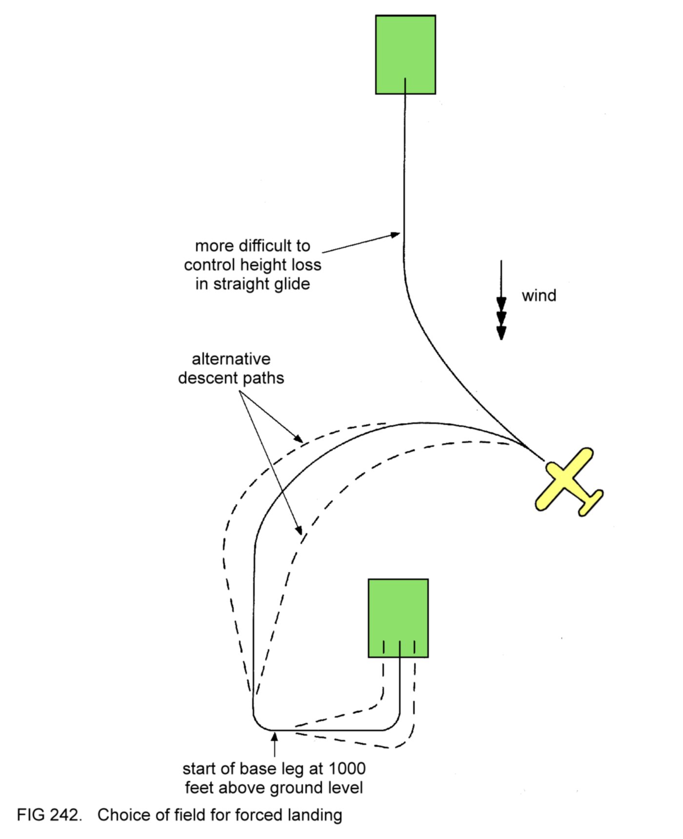
The chosen field should
fulfil as many as possible of the following
criteria:
(a) it should be as
large as possible, both in width and length;
(b) the surface should
be free from buildings, livestock or similar
obstructions;
(c)
the surface should be level and even, preferably green in colour
(signifying grass or young crops) rather than brown (ploughed land) or
yellow (ripe crops);
(d) there should be no
high obstructions (such as electricity cables
and pylons) near the field;
(e)
in sparsely populated regions, the chosen field should be near to a
feature of civilisation, such as a road or settlement, so that
assistance can be readily summoned after landing, if necessary.
A useful mnemonic to
help remember the criteria described above is the
'five esses':
size
shape
surface
slope
surroundings
Of
course, it is probable that the aircraft will not be able to reach a
field satisfying all these criteria. Common sense will dictate the
selection in the circumstances prevailing. Thus in most cases it would
be better to aim to land in a large ploughed field than a small
grass-covered one, since a large field gives the pilot greater chance
of landing within its confines should he misjudge the descent path.
Again,
it would be better to choose a collection of small fields separated
from each other by low fences or walls (leaving the choice of
individual field until a later stage in the descent), rather than a
larger field completely surrounded by buildings or trees.
It is
worth noting that nearly all fields in the open country are smaller in
dimension than the runways at most airfields (Figure 243).
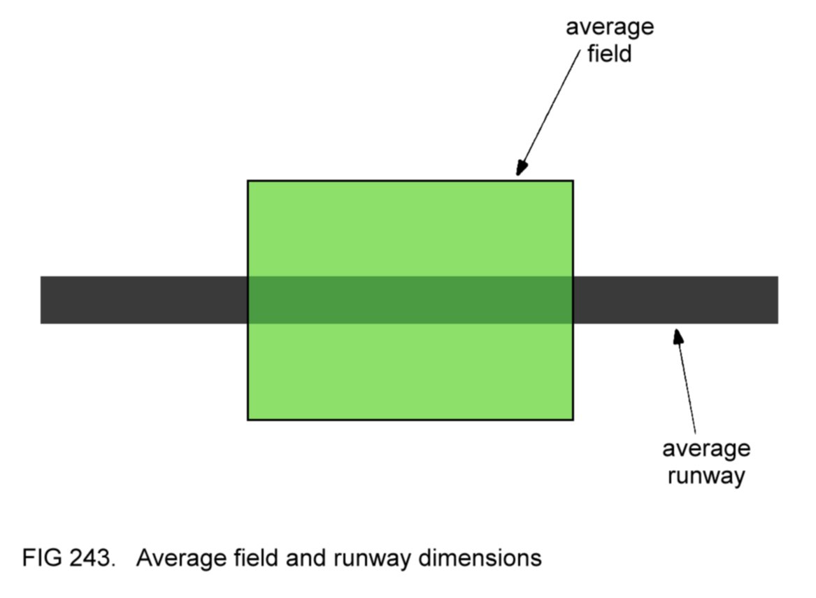
5.1.1.2
Choice of landing
direction
Preferably,
the landing direction should be into wind, as already stated, to
minimise both the groundspeed on touchdown and the length of the
landing run. However, if a considerably longer landing path is
available by landing crosswind, then it would be logical to choose this
alternative.
5.1.1.3
Planning descent
path
As Figure 242 shows, the
pilot should plan to fly a descent path such that the aircraft arrives
at the start of base leg at about 1000 feet above ground level, with
the base leg spaced at about the same distance from the landing path
'threshold' as for a practice glide approach at an airfield.
(Knowledge of the terrain elevation will assist in assessment of height
above ground level when the altimeter is set to QNH.)
Whether a left- or
right-hand circuit should be flown depends primarily
on the height
of the aircraft above ground level and its orientation relative to the
field, bearing in mind that the intention is to arrive at the start of
base leg at about 1000 feet. In the situation shown in Figure 242 a
right-hand circuit would be chosen if there were insufficient height
for a left-hand circuit to be flown (Figure 244).

5.1.1.4
Attempting to
rectify failure
Note
that the propeller will probably continue to windmill, driven round by
the airflow, even after total engine failure. If this is the case, no
attempt should be made to use the engine starter, since serious damage
would probably be caused to both engine and starter.
Instead, the
pilot should carry out the specified cause-of-failure checks to try to
restore power. As previously stated, engine failure is most likely to
occur as a result of pilot mismanagement. Examples of mismanagement are
allowing the fuel tank supplying the engine to run dry, failure to
enrich the mixture after descent from cruising height and inadequate
use of the carburettor heat control to prevent ice formation in the
carburettor. The cause-of-failure checks are designed primarily to
rectify such mistakes. Typically, they include the following actions:
(a)
examine the fuel cock selection and fuel quantity gauges. If the
aircraft has more than one tank, change the fuel cock selection to
another tank containing fuel. This action will restore power if the
cause of the failure was a blockage in
the pipe line from the tank originally selected;
(b) switch on the
electric fuel pump (if fitted), in case the
engine-driven pump has failed;
(c) set the mixture
control fully rich;
(d) set the carburettor
heat control 'on';
(e) check that both
magnetos are switched on.
If
the propeller has
stopped, and the engine failure is not because of
obvious mechanical defect, it would be logical to use the starter to
try to re-start the engine after carrying out the cause-of-failure
checks.
5.1.1.5
Impact checks
If the aircraft is
damaged on
landing to the extent that fuel tanks or pipe lines rupture, there will
be a risk of fire from the spilt fuel.
To minimise this hazard,
the
impact checks should be carried out prior to landing. The checks are
designed primarily to render the aircraft and its components
electrically 'dead', so that no sparks can occur to ignite spilt fuel.
Two
further items included in the impact checks are, firstly, ensuring that
the pilot and his passengers have their harnesses fastened tightly, and
secondly, unlatching the cabin doors to facilitate evacuation after
landing in the event of distortion damage to the fuselage.
A typical sequence for
the impact checks is:
(a) select fuel cock off;
(b) switch off magnetos;
(c) switch off master
switch;
(d) check harnesses
tight;
(e) unlatch cabin doors.
Of
course, if the engine is still capable of producing residual power, it
would be logical to delay items (a) and (b) in the impact checks until
the last moment, in case the pilot finds that he has to use this power
to reduce the rate of height loss after misjudging the descent path.
5.1.1.6
Flying the
descent path
As
already stated, a descent path should be flown which positions the
aircraft at the start of base leg at about 1000 feet above ground
level.
If it appears that the
height surplus will be excessive at
the start of base leg (in other words, if the aircraft is going to be
much above 1000 feet), the pilot should not correct the
error by
extending the downwind leg greatly, since it may subsequently prove
impossible to reach the chosen field when the aircraft is turned back
into wind on final approach. (This is because the gradient of descent
is steeper when gliding upwind than when gliding downwind.) Instead,
the aircraft should be positioned onto base leg and then turned
slightly away from the field. If necessary, the height surplus can be
further reduced by delaying the turn onto final approach, as shown in
Figure
242.
Conversely, if the
height surplus is
disappearing, the aircraft can be turned slightly towards the chosen
field and, if necessary, turned onto final approach earlier, again as
shown in Figure 242.
On final approach, the
height surplus will result
in the sighting point appearing to be beyond the landing path
'threshold'. Once sure of being able to reach the 'threshold' with a
surplus of height to spare, the flaps can be used (as was described in
4.32.1) to reduce the height
surplus by steepening the descent path.
Note
that so far as use of the flaps is concerned, it is better to lower
them too late rather than too early. Far less harm will be done if the
aircraft runs into the field's far boundary at low speed at the end of
its landing run as a result of touching down well beyond the
'threshold' than if it runs into the near boundary at high speed as a
result of undershooting.
The flare technique is
as already described
in 4.32.3. If the landing
path is restricted in length, application of
brakes may be necessary after touchdown to bring the aircraft to a
halt within the confines of the field. The machine should be steered
clear of any obstructions in its path during the landing run.
(In an aircraft equipped
with retractable landing gear, it is advisable
to
delay lowering the landing gear until the pilot is sure that the chosen
field can be reached, bearing in mind that the extra drag will steepen
the descent path.)
5.1.1.7
Overrunning
Even with maximum
application of brakes, it may well be that the chosen field is not long
enough to bring the aircraft to a halt before it arrives at the far
boundary. One way of trying to avoid overrunning is to increase the
length of the available landing path by steering the aircraft to the
left or right as the boundary is approached (Figure 245).

If not already done, the
first three items of the impact checks listed
in 5.1.1.5 should be carried
out after the aircraft has come to a halt if it has collided with the
boundary (fence, hedge or wall) or any other obstruction during its
landing run.
5.1.1.8
Misjudged
approaches
If it is clear during
base leg or final approach that the aircraft is undershooting and will
not reach the chosen field, no attempt should be made to 'stretch the
glide' by raising the nose to a higher attitude, as this will have just
the opposite effect by steepening the descent gradient. Instead, the
best alternative field within gliding range should be chosen for the
landing.
Conversely, the
situation might arise where it is obvious
to the pilot that the height surplus has become so great that, even
resorting to the tactics of turning away from the field on base leg and
delaying the turn onto final approach, the aircraft will eventually
touch down too far beyond the landing path 'threshold', so reducing the
length of landing path available and increasing the danger of
overrunning. In this case, it would be logical to lower the flaps early
or sideslip the aircraft (or both, if permitted for the particular
design of aircraft) to try to minimise the error. In addition, the
descent path can be steepened by increasing the gliding speed (by
lowering the nose), although this advantage will be offset to a certain
extent by the ensuing protracted hold off phase during the landing, as
the aircraft decelerates to touchdown speed.
If the height surplus
is so great that even these remedies would not prevent a touchdown too
close to the far boundary of the field, then the best course of action
is to choose an alternative field in which a touchdown can be made
closer to the near boundary.
5.1.1.9
Summary of forced
landing procedure
Figure 246 summarises
the sequence of events in the forced landing
procedure.

5.1.1.10
After landing
After
landing, the pilot's first concern should be for his passengers and
himself, summoning assistance if injuries have been incurred.
The aircraft should be
protected from damage by livestock or
sightseers.
(Again, assistance will probably be needed.) Finally, the police (and
if applicable the aircraft owner) should be consulted as to the removal
of the
machine from the field.
5.1.1.11
Engine failure
at low height
We
have seen that the lower the height at which engine failure occurs, the
less time there is available to deal with the situation before the
inevitable forced landing.
If the aircraft is not
much above 1000
feet above ground level, there will clearly be insufficient time to fly
a circuit, and the pilot will probably choose to land in a field upwind
of the aircraft's position. If practicable, a base leg should be
flown, to give greater flexibility in control of height loss (Figure
247).

Common
sense dictates that greatest priority should be given to achieving a
safe landing; the secondary actions described in 5.1.1
should only be
carried out if time permits. If there is clearly insufficient time for
all the secondary actions to be completed, it is probably best to omit
the cause-of-failure checks so that the distress call can be
transmitted and the impact checks carried out.
If
the engine failure
is experienced much below 1000 feet, the pilot should turn the aircraft
into wind and land in the best area available, making further
small turns as necessary to avoid obstructions. In the event of there
being insufficient height for a turn into wind to be carried out, a
landing should be made straight ahead. In either case, the flaps should
be lowered prior to touchdown, if circumstances allow, to minimise the
touchdown speed and the length of the
landing run.
5.1.1.12
Engine failure
after take-off
Perhaps
the worst situation that a pilot might face is engine failure directly
after take-off. The situation is aggravated by the fact that the
aircraft will be in a nose-high attitude, and will very quickly
decelerate to stalling speed unless the pilot immediately lowers the
nose to maintain gliding speed.
If
the aircraft is only just
airborne, the obvious course of action is to close the throttle, lower
the flaps, land on the remaining runway and attempt to stop before the
airfield boundary is reached, if necessary resorting to the tactics
described in 5.1.1.7 to
lengthen the available landing path. These
latter considerations also apply to the case of a take-off rejected at
high speed (refer back to 4.28.5).
If the engine failure
occurs during the climb-out, the pilot should lower the nose to
maintain gliding speed and attempt to land in the best area available
ahead of the aircraft. Although small turns might be necessary to
reach a suitable area for landing or to avoid obstructions, or to turn
into wind after a crosswind take-off, no attempt
should be made to
turn
back to the airfield, since there may be insufficient height to
complete the manoeuvre, and in any case the aircraft will contact the
ground at high speed because of the tailwind. Figure 248
illustrates the
point.

Should time permit
during the descent, a distress call can be
transmitted and as many as possible of the impact checks carried out.
If circumstances allow, it is advisable to lower the flaps prior to
touchdown, to minimise the touchdown speed and the length of the
landing run.
5.1.2
Further
considerations
The forced landing
procedure described above has been evolved over many years and in most
situations gives the pilot his best chance of successfully achieving a
safe landing after engine failure. However, it is possible that
circumstances demand modification of the procedure described. Even
though common sense may dictate departure from this procedure, it is
worth remembering that the
first priority must always be to attempt to
achieve a safe landing. All other considerations are of secondary
importance.
If
a forced landing in a heavily wooded area (such as a
forest) is unavoidable, the pilot should try to land the aircraft onto
the tree tops at the lowest speed possible. In other words, the
aircraft should be brought to a stall just above the trees. The more
supple branches in the upper regions of the trees will help to cushion
the impact. This technique is also probably the best to adopt if forced
to land on uneven or rocky ground.
Finally, it will be
appreciated
that flight over towns and cities should be at such a height as would
allow a forced landing to be made clear of the built-up area in the
event of total engine failure.
5.1.3
Practising forced
landing procedure
The
pilot can practise the forced landing procedure by closing the throttle
to simulate engine failure. He should remember to clear the engine
periodically during the glide. The impact checks should be simulated
(rather than actually carried out) and the procedure discontinued at a
safe height above ground level; the success or otherwise of the
practice can be gauged without the need to continue the glide down to
ground level.
5.2 THE
PRECAUTIONARY
LANDING
If for some reason a
pilot in cruising flight must land before reaching
an active airfield he should carry out a precautionary
landing.
Reasons might include:
(a) shortage of fuel;
(b) deteriorating
weather;
(c) approach of night.
The reader will agree
that these predicaments should not arise
if
the pilot has planned and managed his flight properly.
If it proves impossible
to be able to land at an active airfield, the
second best choice might be a disused airfield, although it should be
remembered that many of these are in various degrees of dilapidation.
As a last resort, the aircraft will have to be landed in a field.
When it becomes clear
that a precautionary landing is unavoidable, the
first action should be to decide how much time is available for
searching for a field, remembering to allow perhaps 15 minutes
for inspection of the field prior to landing. Flying in a downwind
direction will allow a greater ground distance to be covered in the
time available and so present a larger choice of fields.
If fuel remaining is the
limiting factor, the aircraft should be flown
at the IAS for maximum range. If deteriorating visibility is the
problem, with the earth's horizon not clearly defined, it
will probably be best to fly at a safe low speed, with the
flaps at 'maximum lift', to give the pilot a better view ahead and more
time to detect and avoid obstructions or higher terrain. Attitude
control will be more difficult and will require greater concentration
in these conditions.
The chosen field should
fulfil as many as possible of the criteria
listed in 5.1.1.1;
it should
be carefully inspected for suitability (this also applies to a disused
airfield, of course) and the landing direction chosen (preferably into
wind).
An approach should be
made towards the intended landing path and the
aircraft flown at a safe low speed, with the flaps at 'maximum lift',
along the landing path on the right-hand side so that it can be
inspected more closely. During this inspection run, the pilot should
not neglect to monitor his ASI and to watch ahead periodically for the
presence of obstructions. Satisfied that the landing path is
acceptable, the pilot can go around and fly another circuit and
approach.
A normal powered
approach and landing should be carried out, unless the
available length of the landing path necessitates a short landing. If
the aircraft is damaged during the landing, the impact checks should
be carried out after it has come to rest, and the machine evacuated.
Subsequently, the considerations in 5.1.1.10
apply.
5.3 ENGINE
FIRE
In modern aircraft,
engine fire is
even rarer than engine failure. Smoke or flames coming from the engine
compartment are indicative of engine fire. It is most likely to be fuel
or oil that is actually burning (possibly because of a broken pipe
line), and so the logical course of action is to cut off the
supply of fuel and shut down the engine, as directed by the specified
engine
fire drill,
to try to extinguish the fire. (Most light aircraft
are not equipped with engine fire extinguishers.)
5.3.1
Engine fire in the
air
If
the symptoms of engine fire are observed during flight, the pilot
should immediately carry out the engine fire drill specified for his
aircraft. The conscientious pilot will know the drill from memory. A
typical engine fire drill might proceed as follows:
(a) close throttle;
(b) select fuel cock off;
(c) switch off electric
fuel pump;
(d) set mixture control
to 'idle cut-off';
(e) switch off magnetos.
With
the engine shut down, the pilot will be obliged to carry out forced
landing procedure (omitting the cause-of-failure checks, of course).
Under no circumstances should the engine be restarted, as the fire is
likely to recur.
After landing, the
aircraft should be evacuated as quickly as possible.
5.3.2
Engine fire on the
ground
If engine fire occurs
whilst the aircraft is on the ground, the
following actions should be carried out by the pilot:
(a) if moving, bring the
aircraft to a halt and apply the parking brake;
(b) carry out the engine
fire drill;
(c) order the evacuation
of the passengers;
(d) transmit a distress
call;
(e) switch off master
switch;
(f)
if near other aircraft or buildings, release the parking brake (to
enable the machine to be pushed clear of them by the airfield fire
crew);
(g) evacuate the
aircraft.
After evacuation, the
pilot
should keep himself and his passengers well clear of the aircraft and
let the fire crew deal with the situation.
5.4 CABIN FIRE
Even
though flames may not be visible, smoke is indicative of fire. The most
likely cause of fire in the cabin is overheating of a component in
the electrical system as a result of malfunction. Most light aircraft
are equipped with a fire
extinguisher in the cabin for use in such situations.
Before taking
any action, the pilot must decide whether or not the fire has an
electrical source, assuming that it does so if any doubt exists. Then
the specified cabin
fire drill
should be carried out. A typical drill
might proceed as follows:
(a) if the source of
fire is electrical, switch off master switch;
(b) use extinguisher at
source of fire, if necessary;
If the fire is
extinguished:
(c) open all available
fresh air vents fully to ventilate cabin;
(d) arrange to land at
the nearest suitable airfield.
If the fire cannot be
extinguished:
(c) initiate a rapid
descent;
(d) transmit a distress
call;
(e)
open all available fresh air vents fully to ventilate cabin. If this
action increases the intensity of the smoke or flames, the vents should
be reset as before;
(f) land in the best
available field (preferably
an airfield) in the vicinity. (Engine power will be available, of
course, should it be needed.)
5.4.1
Further
considerations
If an
electrical fire has been successfully extinguished, further use of the
electrical system should be kept to a minimum. In particular, no
electrical service should be used if it is suspected that that service
may have been responsible for the fire. When it is desired to make use
of one of the services, the following procedure should be adopted:
(a) switch off all
electrical services except that intended for use;
(b) switch on master
switch;
(c) use service as
desired;
(d) when finished with
service, switch off master switch.
In
the event of an electrical fire which cannot be extinguished, it will
be necessary to switch on the master switch briefly to transmit a
distress call.
The rapid descent
technique is employed to bring the aircraft down to
ground level as quickly as possible. One method is to close the
throttle, lower the flaps and fly the aircraft at the flap
limiting
speed to maximise drag.
5.5 DITCHING
Whenever a
single-engined aircraft is flown beyond gliding distance from land,
there is always the possibility of having to ditch the machine in the
water, for example after engine failure. During such flights, all
occupants of the aircraft should therefore wear lifejackets
(uninflated). As an extra precaution, many pilots carry an inflatable
dinghy in their aircraft when flight over water is intended and some
wear immersion suits and ask their passengers to do likewise. If
ditching is inevitable, the following procedure should be adopted:
(a)
fly towards any shipping in the area, or towards the nearest land if
there is no shipping, flying at minimum gradient gliding IAS and using
whatever engine power is available;
(b) transmit a distress
call;
(c) carry out the
cause-of-failure checks if engine failure has
occurred for reasons unknown;
(d) carry out the impact
checks prior to touchdown;
(e)
attempt to touch down at the lowest possible speed (stalling the
aircraft just above the surface), landing along the swell if the wind
is light, or into wind if it is strong;
(f) leave the aircraft
and inflate the lifejacket(s) (and dinghy).
5.6 LANDING
GEAR
EMERGENCIES
It
is usual design practice for aircraft with hydraulically- or
electrically-operated landing gear retraction mechanisms to have an
alternative means of lowering the landing gear after failure of the
normal mechanism. The alternative is often manual in operation.
If
one or more of the wheels fails to lock in the 'down' position when the
landing gear is lowered, recycling
the landing gear (that is,
retracting and then lowering it again) may cure the fault. Recycling
should not be attempted, however, if it is suspected that the
retraction mechanism is damaged.
Of course, it may well
be that the
wheels are in fact all locked down, but that the indicator lights are
faulty. Flying the aircraft past the airfield control tower will
allow ground-based personnel to observe any obvious landing gear
defect. If any doubt exists, the pilot should assume that the wheel(s)
in question are not locked down.
Whenever a landing must
be carried
out with one or more of the wheels not locked down, the impact checks
(5.1.1.5) should be carried
out before landing, leaving the switching
off of the fuel cock and magnetos until immediately prior to touchdown.
It is generally better to land on a hard runway rather than on grass as
less damage is likely to be incurred by the aircraft, and therefore
less harm caused to the occupants. If not already done, the impact
checks should be completed after the aircraft has come to rest. The
machine should then be evacuated.
If the landing has to be
made with
all three wheels in the 'up' position the hold off should not be
prolonged. In other words, the aircraft should be allowed to touch the
runway gently in a flatter attitude than normal, to prevent the nose
dropping violently to the ground after the tail has touched.
If
it is the nosewheel that has failed to lock down, a normal touchdown
should be made on the mainwheels, and the nose then held clear of the
ground as long as possible using the elevators.
In the case of one
of the mainwheels failing to lock down, it may be advantageous to
retract the landing gear again and carry out a 'wheels up' landing in
order to minimise the problem of directional control after touchdown.
On some aircraft designs, however, the landing should be carried out
with as many wheels locked down as are available. The Flight Manual
will explain the best procedure to adopt.
Whenever
a landing has to
be made with only one mainwheel locked down, the ailerons should be
used during and after touchdown to prevent the other wing from touching
the ground. When ground contact can no longer be avoided, the pilot
should be prepared for the swing that will occur towards the grounded
wing. Use of the nosewheel steering (if available) and rudder will help
to minimise the swing, although it may prove impossible to prevent the
aircraft leaving the runway. This consideration should be borne in
mind when choosing the runway intended for landing - it is clearly
desirable to have a minimum of obstructions to the side of the runway.
6 THE FLIGHT MANUAL
The
Flight Manual is the main source of technical information for any
particular design of aircraft. Familiarity with this information will
enable the pilot to operate his aircraft safely and efficiently.
Broadly speaking, the
Flight Manual can be divided into four parts,
dealing with:
(a) a technical
description of the aircraft and its components;
(b) limitations;
(c) performance;
(d) loading.
6.1
TECHNICAL DESCRIPTION
The general arrangement
of the aircraft and its components will be
described, including any special points of interests. The Flight Manual
will also include checklists for use during normal operating
procedures and during emergency procedures.
The
Flight Manual will state the grade of fuel required and the rates of
consumption for various settings of the engine controls. The grade of
oil required and the maximum permitted rate of consumption will also be
stated.
6.2
LIMITATIONS
The Flight Manual will
state the various
airframe limitations (refer back to 4.1)
and the engine operating
limitations (refer back to 4.2.3).
6.3
PERFORMANCE
We have seen
that, to optimise the aircraft's performance, it is often necessary to
fly the machine at specified indicated airspeeds.
The Flight Manual will
specify the correct IAS for:
(a) maximum range (an
optimum altitude may also be stated);
(b) maximum endurance;
(c) maximum rate of
climb;
(d) maximum gradient of
climb;
(e) optimum climb with
flaps at 'maximum lift';
(f) minimum gradient of
glide;
(g) take-off with flaps
up, and with flaps at 'maximum lift';
(h) powered approach,
and flapless approach;
(i) arrival at the
runway threshold after powered approach, glide
approach, flapless approach and for short landing.
Also stated will be the
power-off stalling speed (IAS) in straight and
level flight at MTWA with flaps up and with flaps down. As we have
already noted, these speeds are frequently marked on the ASI.
Additionally, the stalling speed at lower weights may be given.
The actual performance
achieved when flying at the specified speeds
depends upon other factors. The Flight Manual contains graphs which
enable the pilot to assess his aircraft's performance (for example,
gradient of climb) in the circumstances prevailing. Perhaps the most
important performance consideration for the pilot of a light aircraft
is the adequacy of the airfield for take-off and landing. In other
words, the pilot will want to be sure that the runway intended for use
is long enough. For most light aircraft designs it can be assumed that
a runway long enough for take-off will also be sufficient in length for
landing under the same conditions. Accordingly, we shall consider the
factors affecting the length of take-off run required to become
airborne.
6.3.1
Length of take-off
run required
By reference to the
appropriate graph in the Flight Manual, the pilot
can calculate the length of runway required to become airborne. The
length of the take-off run depends upon:
(a) wind component;
(b) air density, in
other words, airfield elevation and air
temperature;
(c) aircraft loaded
weight;
(d) flap position;
(e) gradient of runway;
(f) nature of runway
surface.
To illustrate these
factors, let us take the example of a typical light
aircraft, loaded to 800 kg, taking off from an airfield at sea level
in ISA conditions (air temperature 15°C) with no wind component. The
performance graph for this particular design of aircraft shows that, in
these circumstances, the machine requires a take-off run of 280 metres
(m) to become airborne. Throughout the take-off, the aircraft's TAS
will equal its IAS (because there will be no density error) and its GS
will equal its TAS (because there is no wind component). The
design in our example has a take-off speed of 60
knots IAS. At lift off, then, the aircraft's TAS and GS will both be 60
knots.
The reader will
appreciate that any factor which increases the GS at
lift off will increase the length of take-off run, and vice versa.
6.3.1.1
Wind component
If the aircraft is made
to take off facing into wind, it is said to
have a headwind component. Taking off in the opposite direction, it
would have a tailwind component. In the former case, the aircraft's GS
at lift off will be less than its TAS, and so the length of the
take-off run will be reduced. In the latter, the GS will be greater
than the TAS, and so the length of take-off run will be increased.
Consider our example
above, with conditions as stated, except that the
take-off is made with a 10 knot headwind component. The GS at lift off
will be 50 knots and the length of the take-off run 250 m, compared to
280 m with no wind component. With a 10 knot tailwind component, the GS
at lift off will be 70 knots and the length of take-off run 380 m - a
considerable increase. Figure 249 illustrates the two cases.
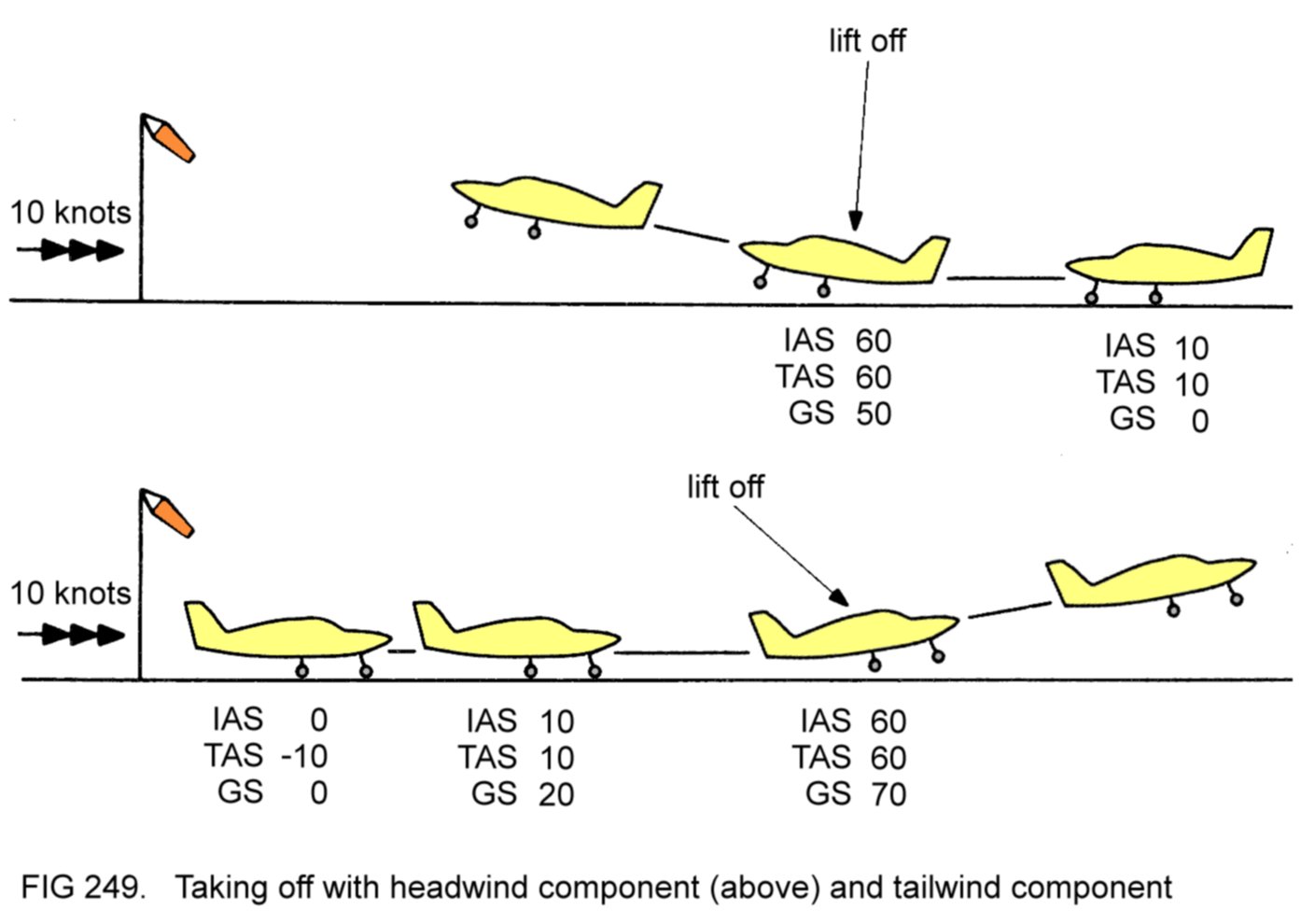
When the wind direction
is coincident with, or opposite to, the runway
direction, it is easy to assess the headwind or tailwind component,
because these quantities will be exactly equal to the wind strength.
(Remember that the wind direction is the direction from which the
wind
blows.) In crosswind conditions, the pilot will need to refer
to a wind component table to assess
the headwind or tailwind component. Such a table is shown in Figure 250.

Common sense dictates
that take-off should be made with a headwind
component whenever circumstances allow, both to reduce the length of
take-off run required to become airborne and to steepen the subsequent
gradient of climb.
6.3.1.2
Airfield elevation
The higher an airfield
is above sea level, the less the ambient air
density will be. The TAS of an aircraft taking off from an airfield
above sea level will therefore be greater than its IAS. Assuming no
wind component, the aircraft's GS at lift off will equal its TAS and
will therefore be greater than its IAS. This increased GS will result
in a longer take-off run.
A further consideration
is the fact that the aircraft's engine will
deliver less power with the throttle fully open than at sea level
(because the air density is less), so reducing the acceleration during
take-off and further increasing the length of the take-off run.
The aircraft in our
example, taking off from an airfield 2000 feet
above sea level in ISA conditions (air temperature 11°C) with no wind
component, will require a take-off run of 360 m, compared to 280 m at
the sea level airfield.
6.3.1.3
Air temperature
With increasing air
temperature, the ambient air density at an airfield
becomes less. So, for any particular IAS, the aircraft's TAS
(and hence GS) will be greater. Additionally, the engine will deliver
less power with the throttle fully open. These two effects will combine
to increase the length of the aircraft's take-off run.
If we consider the case
of our aircraft taking off from a sea level
airfield in ISA+10°C conditions (air temperature 25°C) with no wind
component, the take-off run will be 310 m, compared to 280 m in ISA
conditions.
Of course, in conditions
cooler than ISA, the length of the take-off
run will be reduced.
6.3.1.4
Aircraft loaded
weight
The take-off speed
quoted as an IAS in the Flight Manual applies to the
case when the aircraft is loaded to its MTWA. In practice, take-offs at
lower loaded weights are also made at this speed.
However, the greater the
loaded weight of the aircraft, the slower will
be the acceleration during the take-off run and so the greater will be
the length of the take-off run.
The aircraft design in
our example has a MTWA of 1000 kg. When loaded
to this weight and taking off from a sea level airfield in ISA
conditions with no wind component, the length of the take-off run will
be 340 m, compared to 280 m when loaded to 800 kg.
6.3.1.5
Flap position
The Flight Manual will
specify the recommended flap position for
take-off, to which the stated performance figures will relate.
For most aircraft
designs, the take-off run will be shorter when the
flaps are set to 'maximum lift' than with them up.
6.3.1.6
Gradient of runway
As a general rule of
thumb, the length of the take-off run is increased
(or decreased) by 10% for every 1° of runway slope uphill (or downhill)
because of the slower (or faster) acceleration.
6.3.1.7
Nature of runway
surface
The Flight Manual's
take-off run performance figures usually relate to
a tarmac or concrete runway. A dry, short-cut grass surface will
slightly retard the aircraft's acceleration, so increasing the length
of the take-off run. Long grass, wet grass or soft ground will further
increase the length of the take-off run.
6.3.1.8
Practical
considerations
It would clearly be
tedious to have to calculate the length of take-off
run required before every flight. Indeed, it is not usually necessary
to do so. Most pilots calculate a 'standard' take-off run requirement
for their aircraft assuming the following circumstances:
(a) no wind component;
(b) an average elevation
for the airfields from which the aircraft is
likely to be operated;
(c) air temperature
warmer (for example 10°) than ISA conditions;
(d) aircraft loaded to
its MTWA;
(e) level tarmac or
concrete runway.
If the available runway
length at an airfield is comfortably in excess
of this 'standard' figure then the pilot will not need to make a full
calculation of take-off run required, since the runway is obviously
long enough for take-off. The safety margin will be enhanced by
ensuring that take-off is made with a headwind component if there is a
wind blowing.
If the available runway
length is only slightly in excess of, or is
less than, the 'standard' figure, it will be necessary to make a full
calculation for the circumstances prevailing. Should the calculated
take-off run requirement exceed the available runway length it is
clearly unsafe to attempt to take off, and it will be necessary for the
pilot to reduce the loaded weight of his aircraft in order to be able
to take off safely.
6.3.2
Obstacle clearance
after take-off
The Flight Manual will
contain graphs enabling the pilot to calculate
the ground distance required from the start of the take-off run to the
point where the aircraft has gained a certain height (usually 50 feet).
When obstacles such as buildings or trees are sited close to the far
threshold of
the runway intended for use, these graphs will allow the pilot to
verify that such obstacles will be safely cleared.
In practice, the pilot
will check that the calculated distance to reach
the specified height in the circumstances prevailing is less than the
actual distance from the start of the take-off run to the obstacle in
question, if necessary reducing the loaded weight of his aircraft to
make sure that this is so.
Again,
many pilots calculate a 'standard' figure for distance required to take
off and climb to the specified height. This figure will ensure safe
clearance over the airfield boundary (fence or hedge) if the boundary
is comfortably beyond this distance.
6.4 LOADING
We have seen the
importance of ensuring before flight that the aircraft
is safely loaded. Two requirements must be complied with:
(a) the aircraft's
loaded weight must not exceed the MTWA specified in
the Flight Manual;
(b) the CG of the loaded
aircraft must lie within the specified limits.
6.4.1
Empty weight and
loaded weight
The empty weight of an
aircraft is its weight when unladen, that is,
with no fuel, oil, persons or baggage on board. The empty weight will
be specified in the Flight Manual. Obviously, the loaded weight is the
sum of the empty weight and the weights of whatever items are loaded on
board.
6.4.2
CG position
Determination of the CG
position is not quite so straightforward as
calculation of the loaded weight, but is not a difficult procedure once
practice has been gained.
The procedure involves
the concept of lever arms and moments. The term
'lever arm' applies to a force and is the distance at which the force
acts from a fixed datum point (Figure 251).

The moment of the force
is the product of its magnitude and its lever
arm:
Moment = Force x Lever
arm
Consider an empty
aircraft and take the extreme nose of the machine
as the datum. It is possible to calculate a moment for the empty
aircraft by multiplying its empty weight by the lever arm,
that is, the distance of the CG from the datum (Figure 252).
This calculation is
performed by the aircraft manufacturer and the
calculated moment is stated in the Flight Manual.
Consider now loading the
aircraft by placing the pilot in his seat in
the cabin. The pilot's moment will be the product of his
weight and his lever arm, as shown in Figure 253.
How can we now determine
the position of the CG of the loaded
aircraft? In fact it is merely necessary to divide the total moment,
that is M(e) plus M(p), by the loaded weight, W(e) plus W(p).
The result of this calculation is
the distance of the CG of the loaded aircraft from the datum.
As equations:
Loaded weight = W(e) +
W(p)
Total moment = M(e) +
M(p)
CG position = Total
moment
Loaded weight
Figure 254 illustrates
the CG positions for the aircraft when empty and
when loaded. In the diagram 'LA' is the lever arm for the loaded
aircraft. Notice that, in this example, the loaded GC position is
forward of the empty CG position because the pilot's seat is forward
of the latter.

If we now add more load
in the form of fuel, oil, passengers and
baggage, the same process is repeated to determine the CG position of
the loaded aircraft.
To illustrate the
procedure let us consider an example. The Flight
Manual of a typical aircraft states the following limitations:
(a) the MTWA of this
aircraft is 1000 kg;
(b) the CG position of
the loaded aircraft must lie within the range
225 to 244 centimetres (cm) to the rear of the datum.
The Flight Manual also
states that the CG datum is the extreme nose of
the aircraft. Figure 255 illustrates the permitted range for the CG
position and shows the positions of the fuel and oil tanks, the cabin
seats and the baggage compartment.

Let us suppose that it
is desired to take off with the following load:
(a) pilot (76 kg);
(b) two passengers, one
in the other front seat (69 kg) and one sitting
behind (88 kg);
(c) three suitcases
(total 43 kg);
(d) 8 litres of oil (the
maximum capacity for this design);
(e) 112 litres of fuel.
To verify that this load
distribution satisfies both the stated
limitations, it is necessary to consult the loading section of the
Flight Manual, where the table shown in Figure 256 is given.

Firstly, we can enter
the weights of the various items of load in the
appropriate column in the table. Note that there is no need to
calculate the weight of oil since this has already been done by the
aircraft manufacturer. 112 litres of fuel will weigh (112 x 0.72) or 81
kg. Note, too, that a maximum permitted baggage weight has been
specified, which must not be exceeded.
Now we can complete the
table by calculating the moment (weight
multiplied by lever arm) for each item. It is interesting to note that
the pilot has been combined with the front seat passenger, because the
lever arm is the same for both. For convenience the moment values can
be rounded to the nearest 100 units without significantly compromising
the accuracy of the calculation. Finally, the individual weights can be
added together to determine the loaded weight, and the individual
moments to determine the total moment (Figure 257).

Immediately it can be
seen that the first loading limitation has been
met, since the loaded weight (954 kg) is less than the MTWA.
The CG position is
determined by dividing the total moment by the
loaded weight:
CG position = 219,800
= 230 cm to the rear of the datum.
954
This answer is within
the permitted range. The intended load
disposition is therefore acceptable. (The change in CG position during
flight as fuel and oil are consumed is negligible and can be
disregarded.)
6.4.3
Practical
considerations
As with the take-off
performance calculations we looked at earlier, it
would clearly be
tedious to have to carry out a full loading calculation before every
flight. In fact it is not usually necessary to do so. Most pilots
prefer to adopt 'standard' loading configurations for which they have
performed full calculations and which they know will satisfy the Flight
Manual limitations. These 'standard' configurations will assume an
average weight for pilot and passengers. It is then necessary to make a
full calculation only when the pilot intends to load his aircraft in a
manner differing from the 'standard' configurations, or if the
individual passenger weights differ considerably from the assumed
average weight (for example, when small children are to be carried).
If such a calculation
shows that the CG position of the loaded aircraft
is ahead of the forward limit, then the pilot can move the CG rearwards
by arranging a more rearward disposition of the intended load (for
example, seating the heavier passengers in the rear seats). Conversely,
a more forward disposition of the load will bring the CG position
forwards if the calculated position is to the rear of the rearward
limit.
6.4.4
Dangers of
incorrect loading
Overloading an aircraft
will reduce its performance (for example,
increasing the length of take-off run and reducing the maximum
achievable gradient of climb). Additionally, the landing gear may be
overstressed when taking off and landing, and the airframe structure if
turbulent air is encountered during flight. The stalling speed will
also be increased.
As we have seen, a CG
position to the rear of the rearward limit will
reduce the
longitudinal stability of the aircraft in flight and will make it
easier for the machine to enter a stall or spin if the pilot handles
the controls carelessly. Furthermore, the aircraft will show greater
reluctance to recover from such a stall or spin.
A CG position ahead of
the forward limit will require a greater tail
down-force to hold the lift and weight forces in equilibrium. In other
words, the elevators will have to be held in a more upward-displaced
position during flight. This may leave insufficient upward elevator
movement when it is desired to pitch the aircraft's nose up. Thus it
may prove difficult to raise the nose for take-off and impossible to
flare the machine for landing.
7 GROUND SCHOOL
SUBJECTS
Besides aircraft
handling skills, knowledge of the theory of
flight and thorough familiarity with use of Flight Manuals, student
pilots training for their
licences will need to reach a high standard of knowledge in various
ground school subjects. These include:
Navigation
Flight planning
Operational procedures
Radio communications
Aviation law
Meteorology
Human performance
Most flight training
organisations offer courses in these subjects as
part of the overall training syllabus for pilot licences.
Also by Julien Evans:
Fiction
Madeleine's
Quest
Chalk
and Cheese
The
Sommerville Case
The
Damocles Plot
Flight
935 Do You Read
Non-fiction:
How
Airliners Fly