BRITAIN’S
WONDERFUL
AIR FORCE
Part 3

CONTENTS
Click on the blue dots  for direct access
CHAPTER
8. WITH
THE COASTAL COMMAND
CHAPTER
9. ARMY CO-OPERATION COMMAND
CHAPTER
10.
MAINTENANCE AND TRANSPORT
CHAPTER
11.
CELESTIAL AND WIRELESS NAVIGATION
CHAPTER
12.
AIR PHOTOGRAPHY IN WAR
CHAPTER
13.
AMERICAN HELP FOR THE R.A.F.
CHAPTER
14.
WEAPONS USED IN ATTACK AND DEFENCE
ACKNOWLEDGMENTS
LIST OF ILLUSTRATIONS
Aircraft
of Coastal Command
Avro
Anson Reconnaisance aircraft co-operate with the fleet
Short
Sunderland flying boat
Constructional
details of the Sunderland
Catalina
flying boat
Details
of the Catalina flying boat
Air/Sea
rescue service at work
Houseboat
for R.A.F. pilots
Layout
of floating rescue station
Details
of high-speed rescue launch
Beauforts
sweep the narrow seas
Blenheims
launch low-level attack
Mine
laying by stealth off enemy shores
Torpedoes
for the Beauforts
Loading
up a Catalina
U-boat
surrenders to a Hudson
Lockheed
Hudson reconnaisance bomber
Sunderland
gunners man their guns
How
they used to do Army Co-operation
Mobile
headquarters
Interpretation
staff at work
Why
a low flying plane is difficult to hit
Lysander
and Henschel 126 compared
Briefing
Mustang pilots
Details
of the long range Mustang
Mustangs
of Army Co-operation Command in flight
Parachute
troops bale out
Troop
transport aircraft in use by Britain and Germany
Disused
mine becomes bomb store
Inside
a repair workshop
At
work on a Lockheed Ventura
Atlantic
Ferry Control
Navigator
of a Whitley bomber
Navigational
maps
The
magnetic compass
Adjusting
a Spitfire’s
compass
Navigator's
chart board
Fixing
the position
Mark
IX averaging sextant
Taking
an observation
Getting
a wireless fix
Navigator
plots his course
Navigation
exercises for observers
Camouflage
revealed by the camera
Inside
a mobile dark room
Rushing
off the first prints
Interpretation
staff at work
How
distortion may occur
Progress
of a raid on Lille
Taking
stereoscopic pictures
Stereoscopic
viewing device
Oblique
and vertical photographs compared
Focal
length of lenses
Theory
of oblique photography
Using
a hand camera for oblique shots
Desert
warfare seen from the air
Mapping
from the air
Berlin
seen by the night camera
Camera
gun in action
Bremen
before and after a raid
Hudson
over Dunkirk
Harvard
advanced trainers
Marylands
in the Middle East
Tomahawk
and Kittyhawk
American
aircraft in service with the R.A.F.
Lockheed Lightning
Details of the Lightning
Principle of the Turbo-supercharger
Boeing Flying Fortress
Bell Airacobra fighter
Consolidated Liberator bomber
The Eagle Squadron
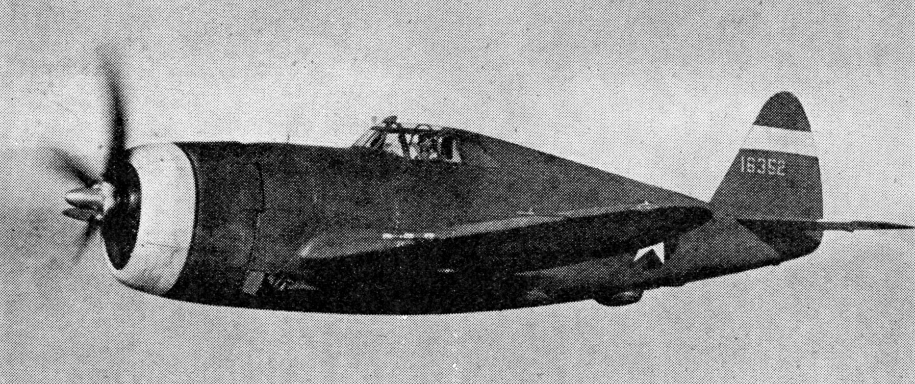
Republic Thunderbolt fighter
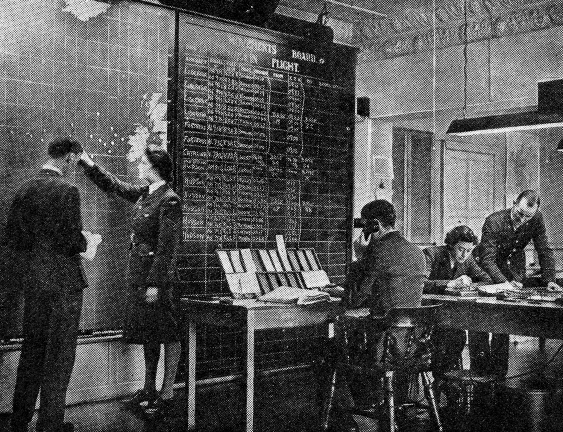
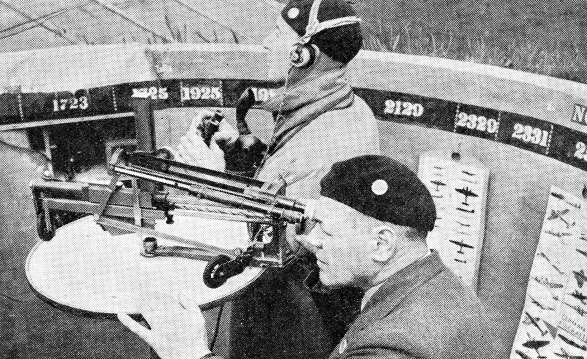
Keeping track of enemy raiders
Duty crew at an observer post
Operations Room at Fighter Command
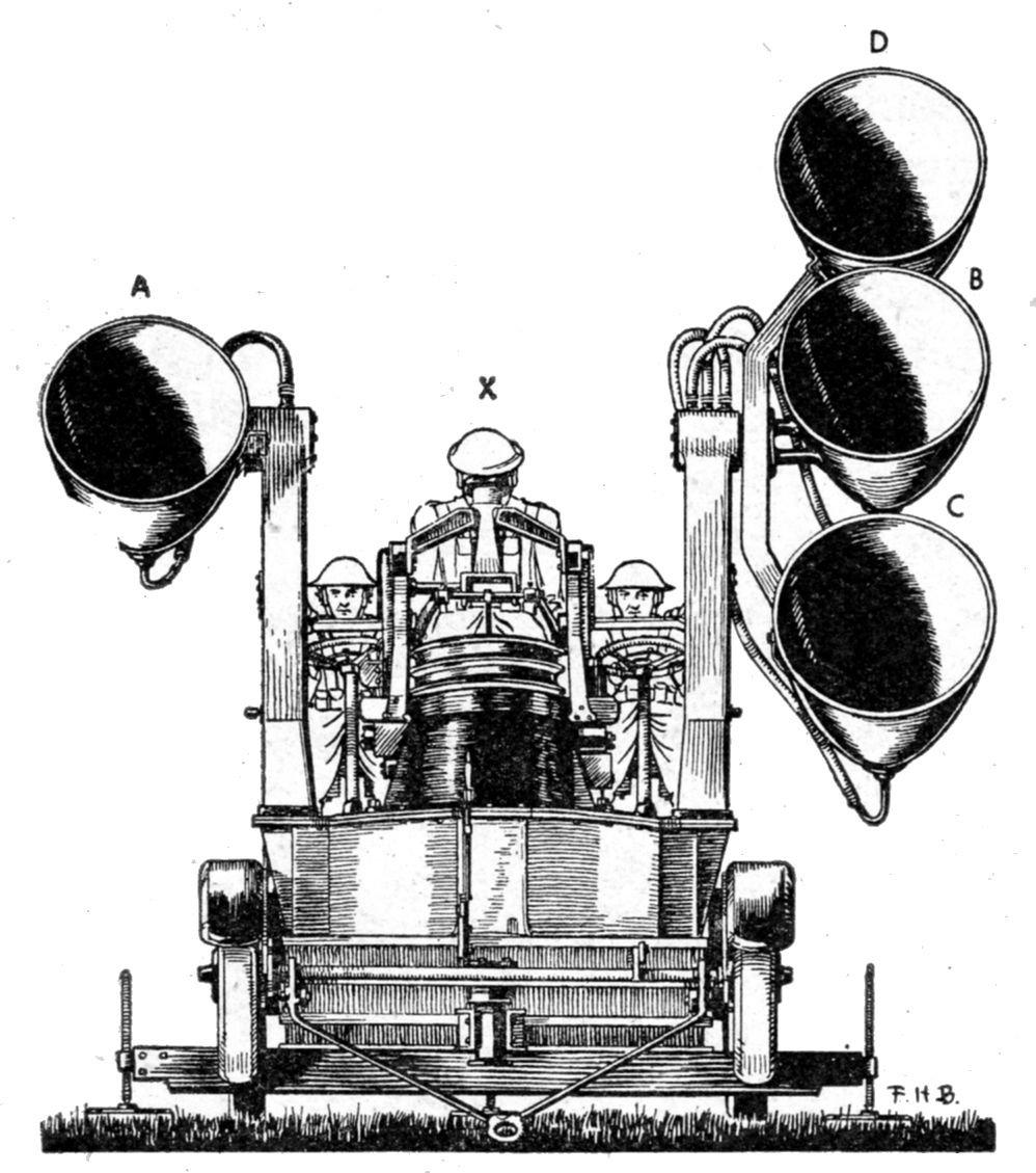
Elements of a sound locator
Diagram of time lag of sound
Construction of a barrage balloon
Inflating a barrage balloon
Device to beat the balloon
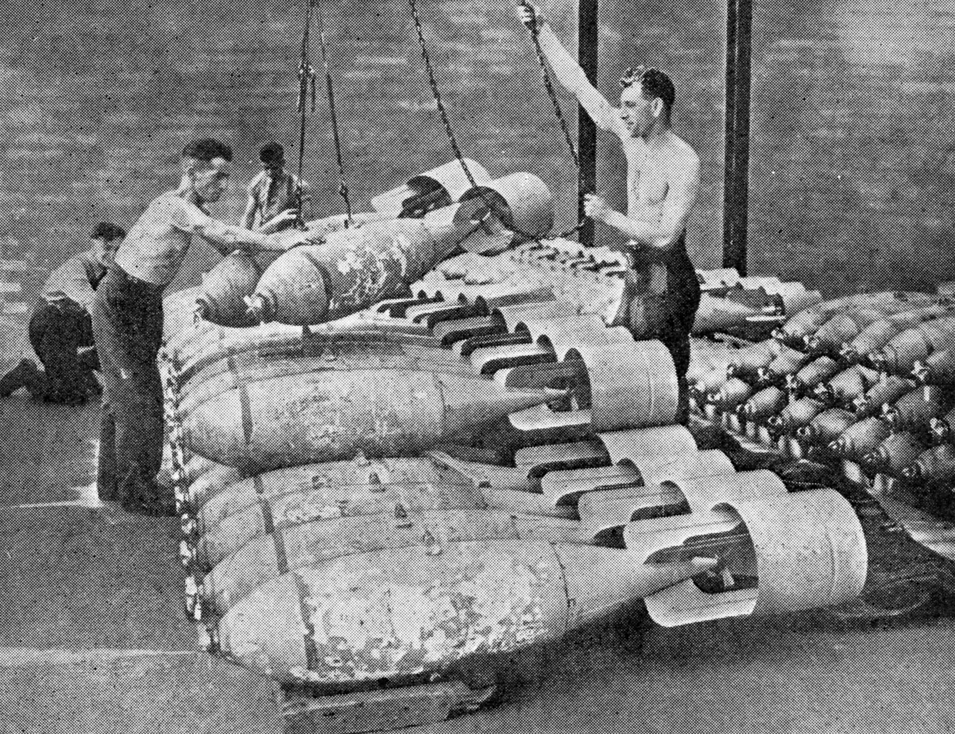
Inside a bomb store
Loading a Beaufort torpedo bomber
SOME
AIRCRAFT OF COASTAL COMMAND
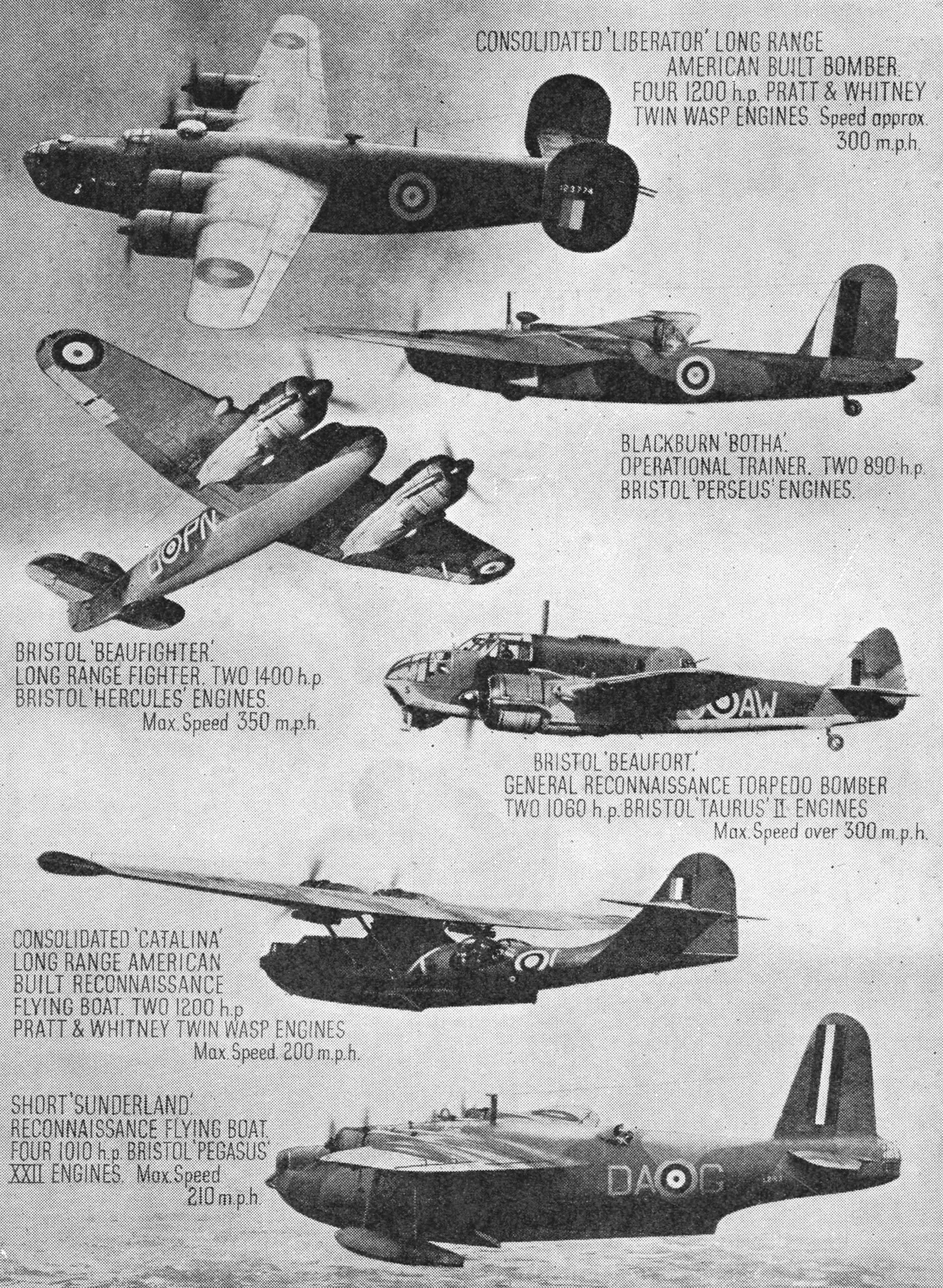
Engine
particulars and top speeds of six types of aircraft used by Coastal
Command. The Bristol Beauforts, with torpedoes slung beneath them, are
famous for low-level attacks on enemy shipping in very bad weather. The
long range Catalinas and Liberators are used for ocean reconnaissance
work and sometimes make flights lasting for anything up to 24 hours
CHAPTER
8
With
the Coastal Command
Early
days of the war. The Scarecrow Patrol. Protection of damaged
submarines. Attacks on enemy battleships. Search for the “Bismarck.”
Seaplanes and land aircraft. Bombing the Channel ports. Photographic
reconnaissance unit. Regional Control. Air/Sea Rescue Service. Beaufort
torpedo squadrons. Work of the Blenheim bombers. Patrolling the enemy
coastline. Dropping mines from the air. Battle of the Atlantic. Thrills
of U-boat hunting. U-boat surrenders to Coastal Command aircraft.
Convoy work in the Mediterranean. A typical day’s flying
BEFORE
war broke out only a few people had realized the possibilities and the
extent of an air war at sea, and in spite of all their efforts they
were unable to convince the governments of those days of its
importance. So the Coastal Command of the R.A.F. started the war with a
grave shortage of both personnel and aircraft. It was equipped with a
few excellent flying boats and some that were not quite so good. Its
principal land aircraft was the Anson (Fig. 1)—a slow cumbersome
reconnaissance bomber that has now reverted to its more natural
function of trainer.
THE FIRST COMBATS
It
was with this equipment that Coastal Command fought, and
fought
well, almost the entire air war of the first nine months of the war. The
aircraft of Bomber Command at that time were confined mainly to dropping
leaflets over enemy territory and gaining experience that was to be
invaluable later on. Fighter Command aircraft during those early months
had almost nothing to fight.
But Coastal Command, ill-equipped as
it was, was in battle from the dropping of the flag. Within a few days
of the declaration of war a Coastal Command Anson had sighted and
attacked a U-boat. Within a few hours of the first minute of the war
Coastal aircraft were escorting shipping convoys and encountering their
first combats with enemy aircraft. On the very first day of the war the
Chief of Naval Staff requested that a Coastal Command pilot be
specially commended for a most useful piece of reconnaissance work
which he had carried out.
AVRO
ANSON RECONNAISSANCE AIRCRAFT CO-OPERATE WITH THE FLEET
Fig. 1.
Avro Ansons, although slow and cumbersome when compared with some of
the later types of aircraft now in use, performed valuable service in
the early days of the war, often attacking ten times their number of
modern enemy fighters. They patrolled thousands of miles of sea in
search of enemy submarines and surface vessels, and so well did they do
their work that the Commander-in-Chief declared that they were his
“secret weapon.” Although Coastal Command still employs a few Ansons,
they are now used in the main as trainers. They have a range of 790
miles, a top speed of 188 m.p.h., and are armed with a single machine
gun in the nose and another in a turret on the top of the fuselage
WORK OF THE ANSONS
It
was at this tempo that Coastal Command fought its war right up to the
days of Dunkirk. And then came its greatest mass effort. The few
aircraft that the men of Dunkirk saw hurtling into battle above them
during the historic evacuation from the beaches were, in the main, the
slow reconnaissance bombers of Coastal Command. Fighting was not their
job, but Ansons pitted themselves against ten times their number and
more of modern German fighters and more often than not the Ansons won.
It was nothing at that time for three Coastal Command aircraft to
report that they had engaged forty enemy aircraft, had shot down
several and had driven the rest away, for the loss of one of their own
number.
With grim humour the pilots coined their own unofficial
motto—“Anson is as Anson does.” The commander-in-chief declared that
they had proved to be his “secret weapon” at that critical time.
“SCARECROW
PATROL”
Even
before that time Coastal Command had pulled off the most successful
bluff ever put over on Hitler, and the aircraft they used were not war
aircraft at all, they were Tiger and Hornet Moths, the elementary
trainers. These small and unarmed aircraft were put on to what was
called the “Scarecrow Patrol,” which succeeded, with no weapon more
lethal than a revolver, in keeping U-boat packs away from our coastwise
shipping.
At the start of the war Germany had about sixty
ocean-going U-boats which were either crossing the North Sea to seek
out the East Coast shipping or were trying to slip out into the
Atlantic.
To the cowering mouse any bird looks like a
hawk, and to the U-Boat any aircraft spells danger. So Coastal Command
sent out their fleet of Tiger and Hornet Moths over the ships, and the
very presence of a pair of wings in the sky was suflicient to force
U-boats to crash-dive and keep even their periscopes below water for
fear that the wake would give them away. The “Scarecrow Patrol”
undoubtedly saved thousands of tons of British shipping. That was
achieved by these trainer aircraft with an endurance of only about two
and a half hours and a petrol consumption of not more than fourteen
gallons for each sortie.
An instance of the thoroughness of
these patrols was a report from one Tiger Moth of “an unidentified
whiteish matter on the water and a bucket partly filled with dirty water
floating near it”—the relics of a German U-boat sailor interrupted at
his ablutions by the necessity of a crash dive.
While the Tiger
and Hornet Moths were holding the fort in this way, however, Coastal
Command was being rapidly re-equipped with aircraft which could kill as
well as find.
They started to come into service just in time, for
when in April and May 1940 the Germans went through Denmark and into
Norway the first phase of the war had finished, and the second came in
with a crash.
The first phase ended perhaps with one of the high lights of the war—the
location of the German prison ship Altmark,
and the rescue of the prisoners by H.M.S. Cossack. This
stirring feat would have been impossible had not the Altmark
been located first by reconnaissance aircraft of Coastal Command, which
ceaselessly scoured the Norwegian coast, night and day, until they
found the ship.
LONG RANGE FIGHTERS
After
the Germans went into Norway, Coastal Command North Sea patrols had to
fly in face of high performance aircraft working from Norwegian
aerodromes, and the Norwegian campaign itself put a very heavy load on
the Sunderland flying boats (Figs. 2 and 3) and other aircraft working
from Scotland and the Shetlands. On top of that, Coastal Command had no
longer to protect shipping only against U-boats but also against enemy
aircraft, and the Command’s first long range fighter squadrons, equipped
with Blenheim fighters, did some magnificent work all along the Norwegian
coasts at the limit of their radius. Beaufighters, however, have now
superseded the Blenheims for this kind of work.
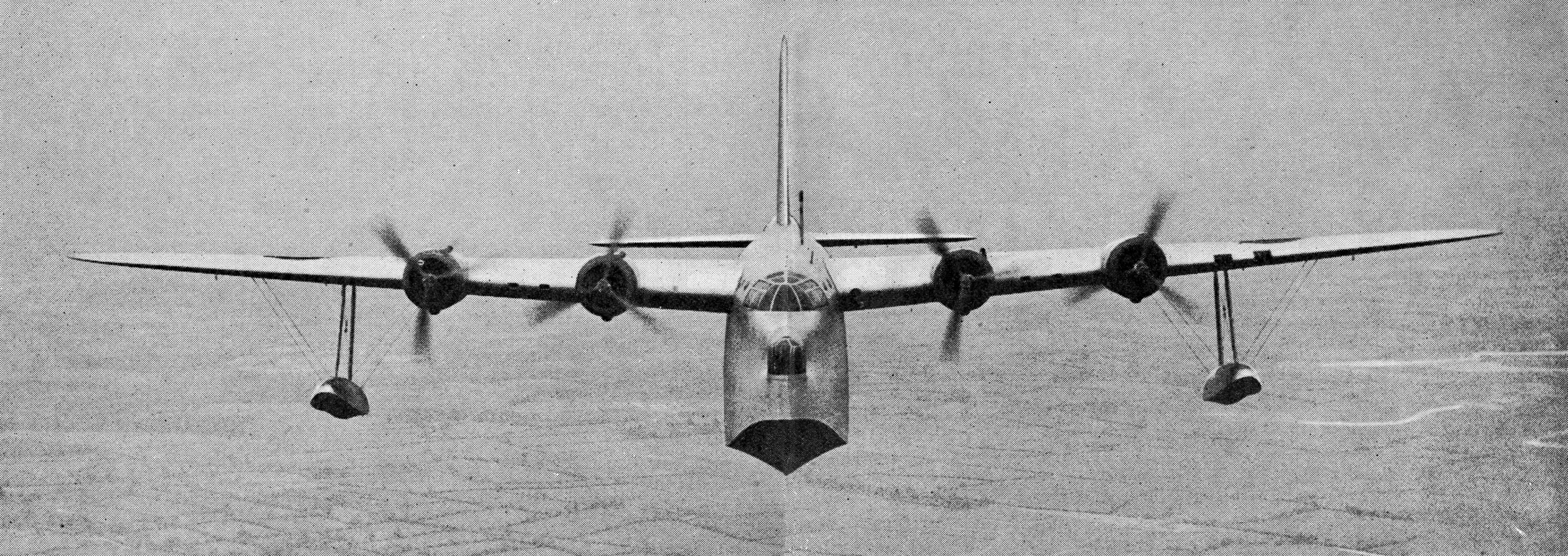
SHORT
SUNDERLAND LONG RANGE RECONNAISSANCE FLYING BOAT
Fig. 2.
The Sunderland is used chiefly for long range reconnaissance. It is one
of the largest aircraft in use by the R.A.F., having a wing span of 112
feet 10 inches, a length of 85 feet 4 inches and a height of
32
feet 11 inches. Its top speed is 210 m.p.h., range 1,780 miles and
duration 16½ hours. Performance has been improved with later models
CONSTRUCTIONAL
DETAILS OF THE SUNDERLAND
Fig. 3.
Diagrammatic drawing of a Sunderland showing interior layout and
accommodation. The front power operated turret retracts backwards, as
shown by the dotted lines, to permit of easy mooring. There is also a
four-gun turret in the tail as shown in the inset, and the armament is
supplemented by two flank gun stations each with a single machine gun.
These are illustrated here. The aircraft carries a large
crew and has a ceiling of 20,500-feet
ESCORTING SUBMARINES
As
an instance of the extra tasks that accumulated at about this time,
British submarines were also active in northern waters, facing immense
risks and sometimes, of course, casualties. Not always, however, was a
submarine lost because it was hit. Sometimes, badly damaged though it
was, it could struggle home provided it could stay on the surface. The
danger to be faced, of course, was a further attack by enemy aircraft,
and it was against that danger that Coastal Command protected these
crippled submarines by ceaseless patrols over them in all kinds of
weather. Many British submarines, including the Triumph, and the
French submarine Rubis
were given successful air escort in this Way.
Another
phase of the war began in June, 1940, and imposed a multitude of tasks
on to those of anti-submarine protection of the Atlantic convoys and
anti-aircraft protection of the East Coast convoys. Aerodromes and
harbours in Norway had to be bombed consistently by the American-built
Hudsons which were turned suddenly from reconnaissance work into a
strong bombing force. Farther south Coastal Command aircraft were thown
into the melee along the Dutch and Belgian coasts and over the Channel,
which culminated in covering the evacuation from Dunkirk.
Then,
in July, 1940, came a new grim phase, one which was to continue for
many weary months. The German occupation of France gave the enemy
numerous aerodromes which threatened Britain and also new submarine
bases on the French-Atlantic coast, which gravely threatened her
shipping artery to America. Long range convoy escorts were provided to
meet the air menace to shipping outside the radius of action of
Spitfires and Hurricanes. Long range convoy escorts over the Atlantic
had also to be increased to meet the wearing but absolutely essential
U-boat hunts.
Another difference in this phase was the necessity
of reconnaissance sweeps over the North Sea to prevent German surface
raiders getting out into the Atlantic. On several occasions when
raiders did try to get out it was aircraft of Coastal Command that
spotted them and either drove them back unaided or assisted in turning
them away.
ATTACK ON “SCHARNHORST”
Before the Scharnhorst
earned her notoriety in Brest she was one of the raiders that tried to
put out into the North Sea. A reconnaissance aircraft of Coastal
Command spotted her, and Hudsons and Beauforts of the same Command
immediately set out to the attack. Scharnhorst
was steaming at this time along the Norwegian coast. Besides her naval
escort of destroyers she had an air umbrella of fifty Messerschmitts.
The attacking forces of Hudsons and Beauforts were far fewer in number
and they had to face not only the fifty Messerschmitts but the fire of
the warship’s guns. Quite unperturbed by this they carried out their
successive attacks and scored in all three direct hits on the Scharnhorst, one of
which seriously damaged a gun turret.
The Deutschland—now
renamed the Lutzow—provided
another instance of Coastal Command reconnaissance through the dirtiest
weather. After she had attacked the Rawalpindi she was
picked up by aircraft of the Coastal Command and shadowed over
hundreds of miles.
Later on in the course of the war came the famous tracking of the Bismarck.
It was a Coastal Command aircraft on reconnaissance that first reported
her presence in harbour at Bergen. It was a naval aircraft, however,
which reported that she was gone from Bergen only an hour or two after
she had sailed.
“BISMARCK”
EPISODE
She
was shadowed across the North Sea while British naval forces closed in
on her track, and she was picked up by a Sunderland flying boat just as
she entered into the ill-fated engagement with H.M.S. Hood. The
Sunderland was instrumental in directing other surface ships to the
rescue of the few survivors of Hood.
Then the Bismarck
was lost for twenty-four hours. The biggest air search in history was
at once instituted by Coastal Command, while large naval forces were
steaming from all directions towards the areas in which Bismarck
was believed to be. But still there was no trace of her. The weather
had closed down and visibility was wretched. The aircraft were flying
through storms and gales for hour after hour, far out over the ocean.
To each of them must be given equal praise for the perseverance and
endurance with which they carried out this task. But the one that had
the good fortune actually to find the Bismarck
was a Catalina flying boat (Figs. 4 and 5) which came upon her suddenly
as it emerged from cloud and was at once under fire from the
battleship’s guns.
Although the Catalina had been hit, and suffered damage, it continued
to shadow Bismarck
for several hours until naval forces and naval aircraft could get close
enough to deliver the death blow.

CONSOLIDATED
CATALINA LONG RANGE AMERICAN FLYING BOAT
Fig.
4. The Catalina flying boat is used by Coastal Command for ocean
reconnaissance and convoy work. Although the top speed of 190 miles per
hour of the earlier models was slower than that of the Sunderland, its
4,000-mile range was greater. During the search for the German
battleship “Bismarck” one Catalina remained on patrol continuously for
twenty-seven hours
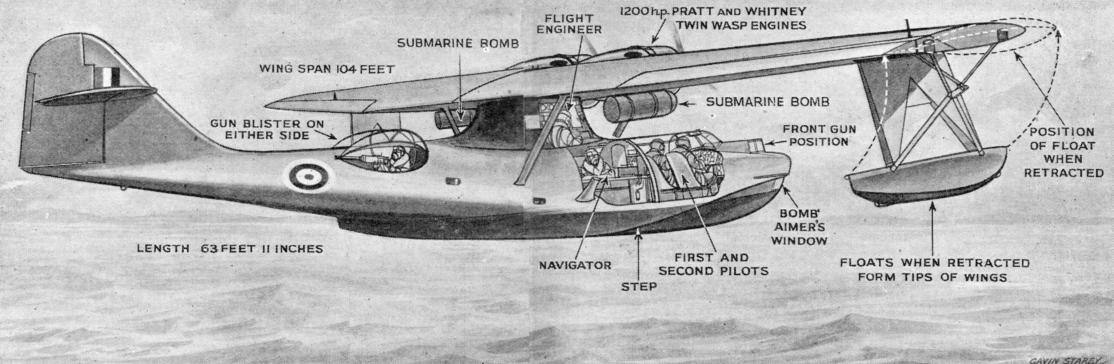
DETAILS
OF LAYOUT AND ACCOMMODATION OF THE CATALINA FLYING BOAT
Fig. 5.
The Consolidated Catalina incorporates some interesting and unusual
features in flying boat design. The floats, for example, retract outwards
to form the tips of the wings, and the rear armament is accommodated in
two large blisters, one on either side of the fuselage. Submarine bombs
are carried externally on racks beneath the wings, as shown
BEAUFORTS ATTACK “DEUTSCHLAND”
There was one other noteworthy clash with a German surface raider. This
was again the Deutschland,
but by then she had been renamed Lutzow.
She was putting out through the Skagerrak and heading for the Atlantic
where most important British convoys were steaming in from America,
when a Coastal Command Hudson on reconnaissance discovered her. She was
surrounded by destroyers.
Torpedo-carrying Beauforts of Coastal
Command were at once dispatched to engage her. Two of them came across
her off the south-west coast of Norway, and they carried out at only a
few feet above the sea one of the most daring attacks of the air/sea
war. “Skidding” over the stern of one of the protecting destroyers
they flew into the right position for the attack and launched
their
torpedoes. It is certain that one of the torpedoes secured a direct hit
amidships. The other almost as certainly found its mark, but bad
weather and the necessity for avoiding the hail of anti-aircraft fire
from the ship prevented the second Beaufort crew from observing the
exact result of their attack. It was sufficient, however, to accomplish
its purpose. Coastal Command reconnaissance aircraft were arriving now
in relays, and they reported the Lutzow
had turned back and was endeavouring at a much reduced speed
to
regain a German port. One of these aircraft, a Blenheim fighter,
shadowed her for many miles, right up the Skagerrak. The torpedoes had
not sunk her—it would be a lucky torpedo indeed that could sink a
modern battleship—but they had forced her into port for repairs. The
Atlantic convoys which she had set out to attack, however, went their
way umnolested, and another telling blow had been struck against German
naval power in the Battle of the Atlantic.
NEW EQUIPMENT
All
this, however, still lay in the future for Coastal Command which, as
the Germans swept westward, found itself ready to meet the many more
gruelling demands which were to be made on it.
Special efforts
had been made to reinforce this Command of the R.A.F. in anticipation
of the ever heavier role it would have to perform in the near future,
and many of its aircraft were brought across to Britain from
America.
It had been re-equipped almost as an air force within
an air force. By the end of the first two years of war Coastal Command
was flying bombers, reconnaissance bombers, flying boats and fighters. It
was equipped with Sunderland, Catalina, London, Lerwick and Stranraer
flying boats together with squadrons of American-built Northrop
seaplanes. Its land aircraft included Lockheed Hudsons,
Beaufort
torpedo-bombers, Blenheim bombers, Liberators, Blenheim fighters,
Beaufighters and a few Ansons not yet turned over to training (see
illustrations here).
Today it is using modern four-engine bombers such as the Halifax.
The
primary performance of Coastal Command had remained, as it had always
been, visual and photographic reconnaissance, but to that basis had
been added striking power. The enemy had felt that striking
power
when he went into Norway and down through Denmark, Holland and Belgium.
As he spread into France he felt it even more strongly, for Coastal
Command aircraft met him over the Channel and Dunkirk. They also took
part in the bombing of the ports which he was occupying.
American
Lockheed Hudsons of one squadron alone hammered at Rotterdam night
after night until they could report that nearly all of the oil
installations which had been left there by the Dutch were now
destroyed. Hudsons and Beauforts ranged at that time to Ostend, Calais,
Boulogne, Cherbourg, and battled away at the harbour installations and
the shipping. At the time of the Dunkirk evacuation itself, Coastal
Command added Army Co-operation to its variety of tasks, and day after
day its aircraft skimmed the battlefields around the allied perimeter,
attacking tanks, armoured columns and gun sites, and shooting up enemy
troops on the ground.
Then, as the threat of invasion deepened
with the passage of months, it was the invasion preparations in the
Channel ports that became the targets. They were bombed by day and by
night. The invasion barges and the shipping being constantly harassed
and destroyed. Soon it was the submarine bases at Lorient to which
Coastal Command turned its attention, and they not only destroyed many
of the installations but bombed several U-boats in harbour there.
TWO SERVICES
But
all this time the primary task of reconnaissance and of convoying
shipping had continued without a break. Even in the stress of these
months of warfare, Coastal Command had conceived and developed two
major services, not only directed to the war effort, but to the
whole techniqiue of flying in the future.
The first of these
two major services is called Regional Control. The greatest enemy of
the Coastal aircraft is not Germany but the weather. And the fight
against the weather goes on without the slightest pause. There have
been occasions when the only aircraft in the air in the whole of
Western Europe have been those of Coastal Command, battling their way
through storms on a reconnaissance flight.
In order to help these
aircraft to get back safely to land in conditions of “non- flying”
weather, Regional Control was devised. It is a system of co-ordinating
the standard blind approach landings and the international Q-code of
call signs. It is an organization which can pick up a returning
aircraft in the thickest fog, lead it away from its fog-bound home
base, direct it to quite another part of the country, and bring it down
safely. It has already saved the lives of hundreds of air crews. When
peace comes again and its secrets can be made known to the world, it
will revolutionize bad weather flying for civil aviation.
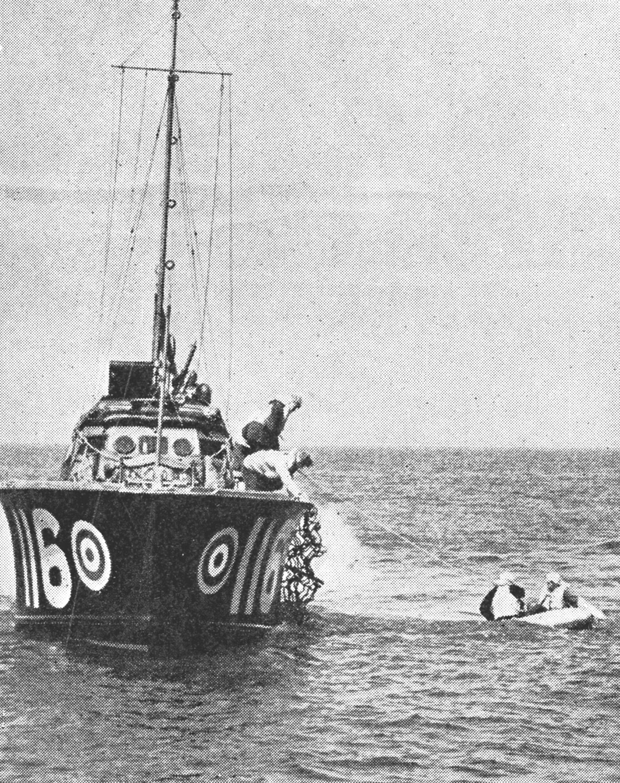
AIR/SEA
RESCUE SERVICE AT WORK
Fig. 6.
Many airmen, like those seen above, who have been forced to land in the
sea, owe their lives to the vigilance of the Air/Sea Rescue Service
which was conceived and developed by Coastal Command. It employs
high-speed launches which work in conjunction with patrolling aircraft
The
second service devised and carried out by Coastal Command in
conjunction with the Admiralty, which is now incorporated in the
Directorate-General of Aircraft safety, was the Air/ Sea Rescue Service
(Figs. 6—9). The waters that divide Britain from her Continental enemy
are friendly indeed, but to returning aircraft at night, badly damaged
perhaps, the crews weary and suffering from strain, the water is an
enemy. A number of aircraft in these circumstances have “come down in
the drink.” Many of their crews have subsequently been saved and
brought safely to shore by the Air/Sea Rescue Service. This
co-ordinates all the air searches for lost crews that are floating
somewhere in a dinghy with the small fleet of high-speed launches which
operate from points all round the coast; and if no high-speed launch is
available the Air/Sea Rescue Service ropes in the lifeboats,
any
ships nearby or any naval forces. Once the lost crew in its dingy has
been located by a searching aircraft, every possible expedient is used
to get a surface vessel to them.
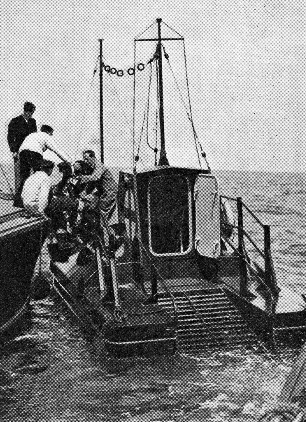
HOUSEBOAT
FOR R.A.F. PILOTS
Fig. 7.
The Air/Sea Rescue Service has anchored floating rescue stations, like
that seen above, in the Channel. Here pilots who have been forced down
in the sea can find shelter and comfort until rescued by one of the
high-speed launches
LAYOUT
OF FLOATING RESCUE STATION
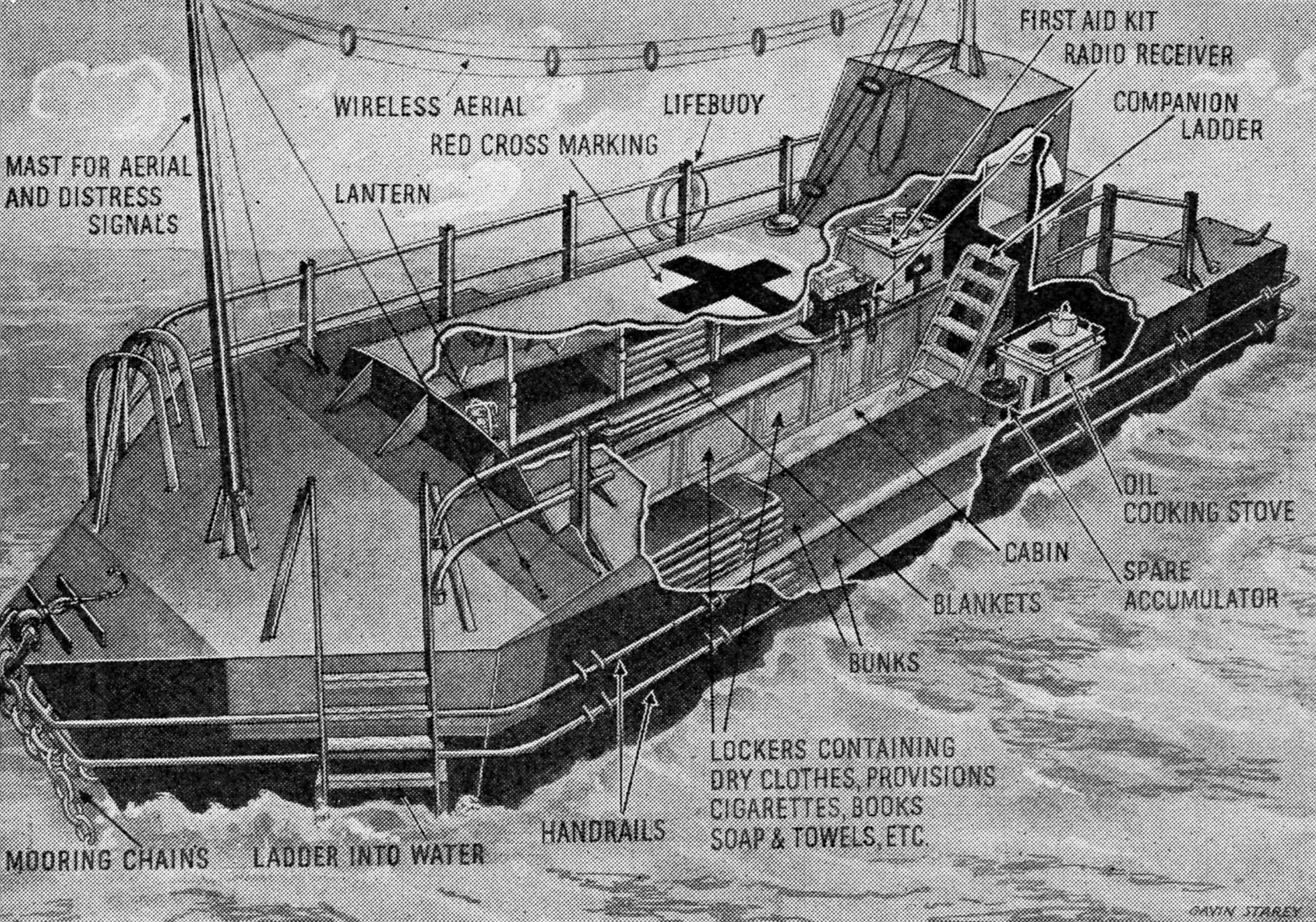
Fig. 8.
Diagram showing general layout of R.A.F. rescue station.
The boats, which are painted yellow and red to make them
visible
from the air, are well provisioned and equipped with food, first aid,
wireless and other comforts. They have been the means of saving many
lives
In
addition to the ceaseless watch kept by patrolling aircraft and the
constant sweeps of the high-speed rescue launches, the Air/Sea Rescue
Service maintains a fleet of floating rescue stations (Figs. 7 and 8).
These are anchored at intervals in waters above which the activities of
British aircraft are most thickly concentrated, and any airmen who are
forced to abandon their machines over the sea and take to their rubber
dinghies, can paddle to these stations and there find food, warmth and
comfort until they are rescued.
The stations are painted bright
yellow and red so that they can be readily recognized from the air.
They are well equipped with blankets, food, reading matter and first-aid
equipment, and there is a wireless set in each. The sterns are made to
slope down into the sea so that the airmen can easily climb abroad and
drag their dinghies after them. They are visited regularly by the
Service’s launches. These floating stations have been the means of
saving the lives of hundreds of airmen—both friend and foe—who have
been fortunate enough to bale out in their vicinity.
These are
both humanitarian services, but Coastal Command has developed no less
formidably in the opposite direction, that of a striking force. The
motto of the Command is “We search and strike.” Much of the time must
necessarily be occupied by the search, but the strike is by no means
forgotten. It is the Coastal Command which thinks always in terms of
the offensive. The most vivid instance of this great offensive
spirit is the constitution of the squadrons of Beaufort torpedo
bombers. They are the most effective striking force of the Coastal
Command, and it is certain that they have one of the most hazardous
jobs to perform.
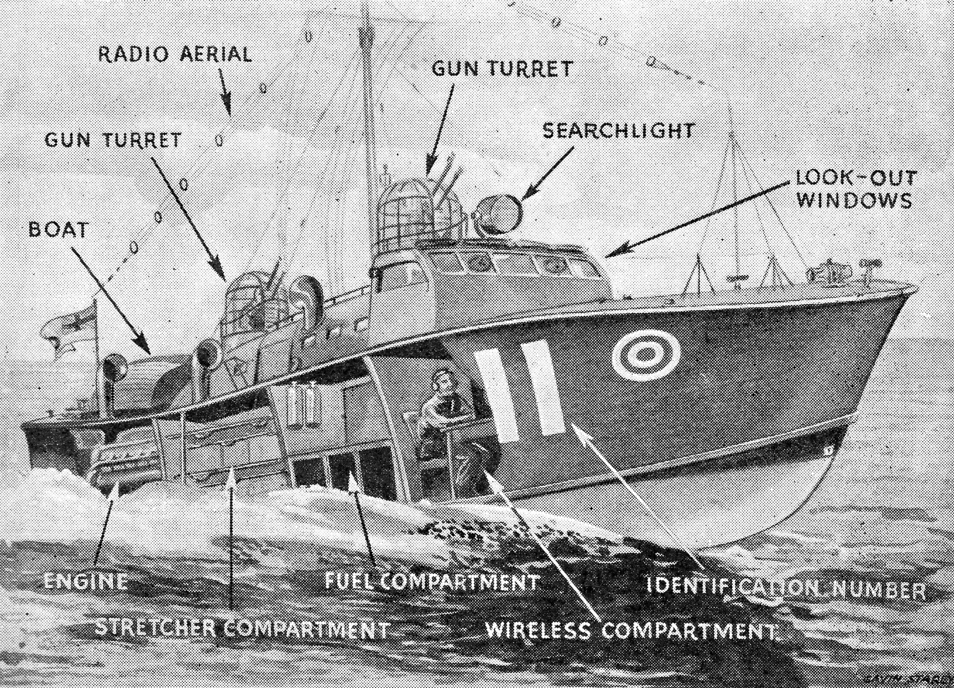
DETAILS
OF HIGH-SPEED RESCUE LAUNCH
Fig. 9.
Rescue launches used by Coastal Command are very fast and well
equipped. That seen above is 65 feet long and is powered by three 500
h.p. engines. It carries a crew of nine
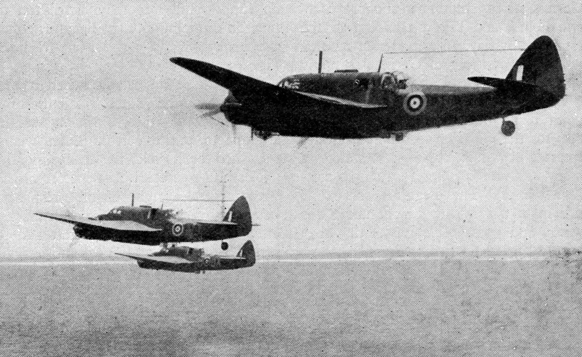
BEAUFORTS
SWEEP THE NARROW SEAS
Fig. 10.
The Bristol Beaufort torpedo bombers seen above are off on an offensive
patrol against enemy shipping. This work calls for great courage and
judgment on the part of the pilots, who have to descend to within a few
feet of the sea in order to release their torpedoes
The Beauforts (Fig. 10), with the torpedoes
slung beneath them, rarely fly at higher than 200 feet, and they make
their attack at close range from a lower height than that. Coastal
Beauforts scour the enemy coastline (and more than the enemy coastline)
from Greenland, through Norway, Denmark, Germany, Holland, Belgium and
France, down to Bordeaux and far out into the Bay of Biscay. They are
the mobile force of the Command. They prefer to fly in bad weather, for
it gives them cover from the ships’ gunfire, and they direct their
torpedoes either by day or night at the shipping with which Germany
must necessarily ply up and down the European coast.
With every
dislocation of the already overcrowded European railway services, the
enemy is forced to attempt more and more coastal transport. A 6,000-ton
merchant ship, for instance, can carry as much as ten long goods
trains, so the advantages of coastline transports are obvious.
The
disadvantages soon became equally obvious to the German seamen, and the
gravest disadvantage of them all was the Beaufort torpedo bomber of
Coastal Command. One squadron alone, early in its torpedo career, sank
31,000 tons of German shipping within a month, and more than
20,000 tons within seventy-two hours. At the end of a year
that
squadron alone had sunk, or seriously damaged 103,000 tons of German
shipping. But the feat was soon eclipsed when Coastal Command
squadrons sank or shattered 100,000 tons of German supply shipping in
about seventy-two hours, and kept on adding to the total day by day. In
a matter of months nearly 400,000 tons of German shipping had been sunk
or disabled.
Every
sortie in a Beaufort means flying point blank into a hail of
anti-aircraft fire, for the German coasters are always escorted by flak
ships—sometimes as many as five flak ships to a single merchant vessel.
The Beaufort makes its run in at a very low height above the water, and
pilots often report that they have managed to turn away only just in
time to miss hitting the bows of the ship they have attacked with their
torpedoes.
The Beauforts sink ships with torpedoes by night as
well as by day, picking them out as dim shadows on a dark sea, or black
shapes creeping across the moon’s path. These torpedo attacks on supply
ships are the normal run of torpedo dropping, but the Beaufort crews
are always ready and eager to hunt bigger game.
There was one instance when it was feared that the German battleships Scharnhorst or the Gneisenau
might attempt to put out from Brest where they had been held for many
months by bombing attacks. A Beaufort attack with torpedoes right
inside Brest harbour was decided upon and brilliantly executed. The
attacking aircraft had to run the gauntlet of terrific anti-aircraft fire
both from the ground defences and the guns of the battleship, yet it
pressed home the attack successfully and almost certainly scored a
direct hit with its torpedoes. Such an attack is a typical example of
the way in which Coastal Command pilots generally press home their
attacks in face of most violent opposition and regardless of their own
safety.
At one stage in the war a squadron of Blenheims and a
squadron of Beauforts were tactically placed so as to command the
English Channel, and they were told that their task was to deny the
Channel to enemy shipping. Those ships that the Blenheims missed—and
since they attacked from about thirty feet high they did not miss
many—were then pursued with torpedoes from the Beauforts (Fig. 11).
Scarcely
a month after the beginning of these operations the crews of both
squadrons were complaining that Jerry never seemed to send them targets
any more. The English Channel had been closed, at any rate for the time
being, to the Germans.
Similar operations followed soon
afterwards off the Dutch islands where there were concentrations of
German supply ships. At one stage a newly formed Canadian squadron,
flying Hudson aircraft, was set to cover this stretch of the coast. When
they had been operating for a little less than a month they had scored
certain hits on nine German vessels with a total tonnage of
approximately 30,000.
After the outbreak of the Russo-German war
another stretch of European coast became an attempted channel for
German supply shipping. This was the south-west corner of Norway,
around which the Nazis tried to send, by sea, supplies to their armies
on the North Russian front. Another Beaufort squadron was given this
route to look after, and its successes were as great as those
of
the sister squadron which guarded the whole of the English Channel.
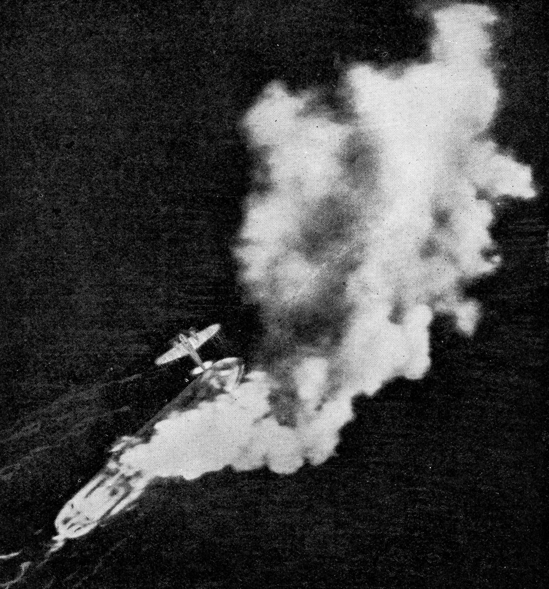
BLENHEIMS
LAUNCH LOW-LEVEL ATTACK
Fig. 11.
The Blenheim seen above has just scored a direct hit on a 2,500-ton
vessel, which is burning fiercely. Such attacks are usually carried out
from a height of about 30 feet
There
is another way of striking at enemy shipping. The Germans used it
against Britain, and Britain in return used it against the Germans.
This method is to lay mines from aircraft in the coastal shipping
routes which the enemy must use (Fig. 12). Much of this work was done
by aircraft of the Coastal Command or naval aircraft working under
their orders. Little is heard of these operations. Their results are
seldom announced, often indeed are not known at the time; but night
after night the mine-laying crews, without any public acclaim and
without even the visual satisfaction of a bombing raid, face conditions
that demand a courage and a fortitude as great as any that can be shown
in the air. The mine laying must be done with precision, at
places
most likely to catch the German coastwise shipping as it creeps
nervously along through in-shore waters, usually under the protection
of coastal batteries.
Some of the aircraft which lay these mines
used to have open cockpits, giving almost no protection against
weather, and in them the air crews sat for hours at a time, almost
unable to move, in temperatures well below zero.
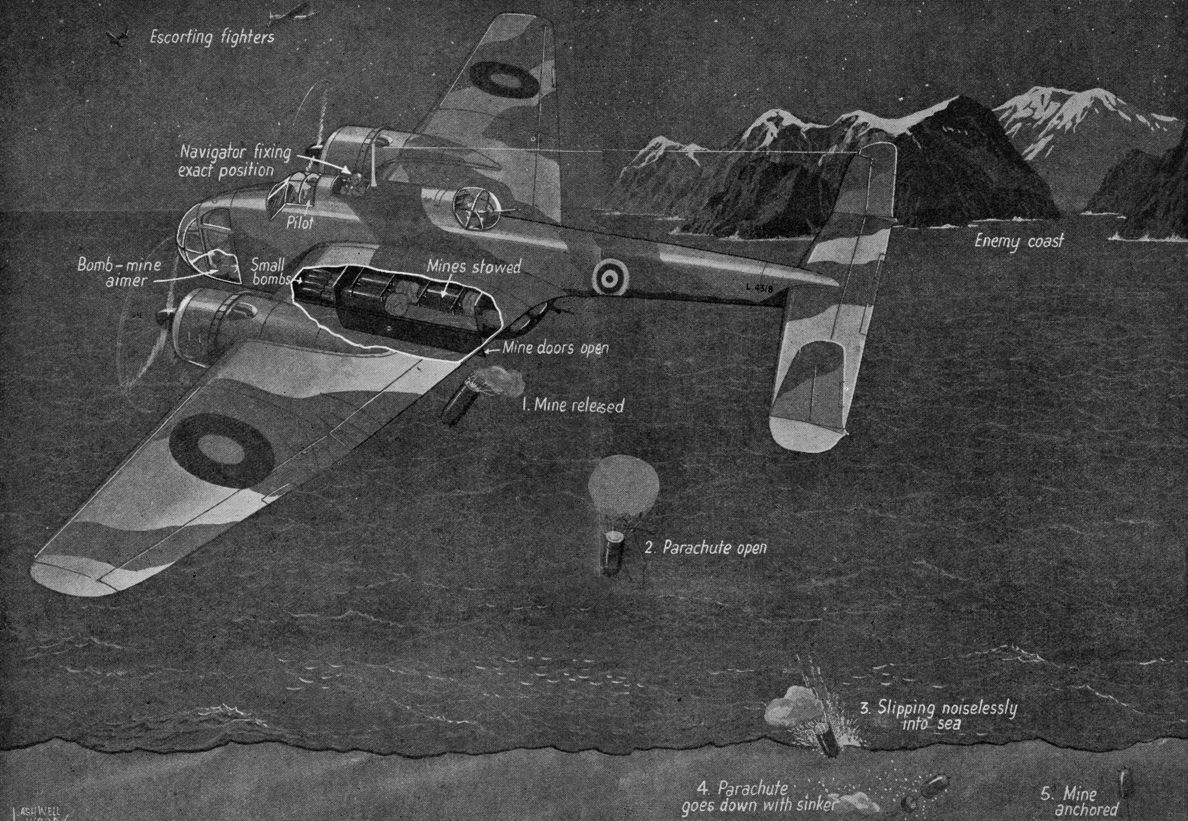
MINE
LAYING BY STEALTH OFF ENEMY SHORES
Fig.
12.
Night after night converted bombers of Coastal Command carry out mine
laying sorties over enemy waters in order to harass coastwise shipping,
and here is a drawing of a low flying Handley Page Hampden long range
aircraft so engaged. Mines enter the sea comparatively gently
and
automatic parachutes are fitted. The mine’s buoyancy and its sinker
combine to locate it at a vulnerable depth. Mine laying calls for the
greatest accuracy by the navigators. The above drawing is reproduced
here by the courtesy of the “Sphere”
The
mines themselves must be laid so close in-shore that the air crews
often find themselves automatically, though quite needlessly, talking in
whispers as they approach. One aircraft, while flying up the coast, was
accompanied for several miles by flashes of light from the cliffs—the
pocket torches of the German gun crews running to their guns. After the
mines have been laid there follow the hazards of a return journey over
the sea, often in terrible weather with the thought of petrol shortage
just below the surface of the mind.
These are the jobs which Coastal Command pilots refer to as “stooge
jobs.” They find them boring and extremely dull.
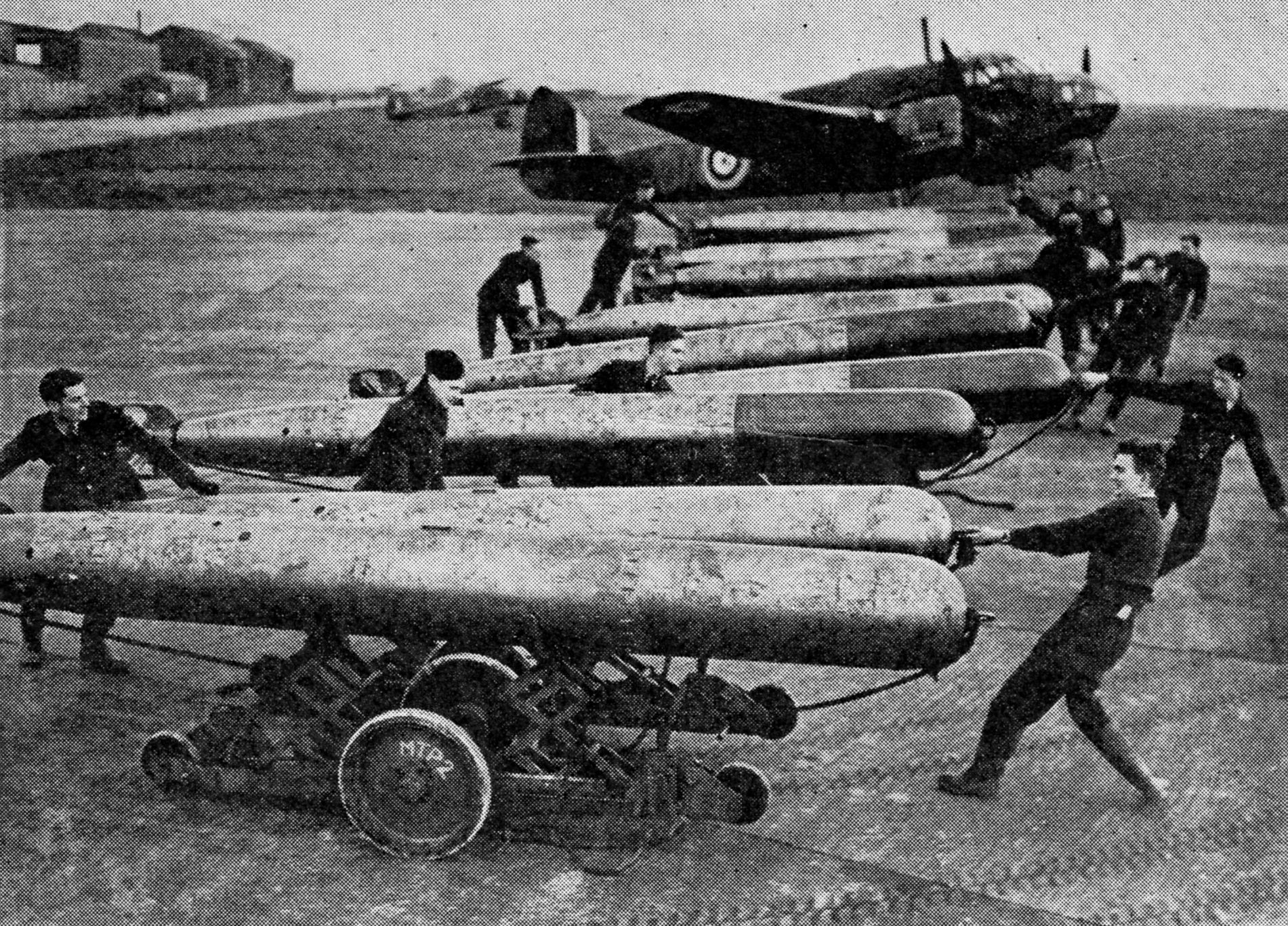
TORPEDOES
FOR THE BEAUFORTS
Beauforts
carry a single torpedo which is stowed inside the fuselage. It is
jacked up into position from special trolleys, like those seen above,
which are being hauled by the ground staff at a Coastal Command
station. Aircraft torpedoes are slightly more robust than naval ones
Little
has been said so far about the biggest battle of all which is being
fought by Coastal Command—the Battle of the Atlantic. Little can be
said, for it is not only in area the biggest battle the world has ever
seen, it is also the most secret battle of history. It is waged over an
area of more than 600,000 square miles (a battle front that no German
or Russian general has ever dreamed of). In essence it is a simple
battle. Britain is trying to bring convoys laden with
supplies,
and often with troops, from the New World to the Motherland. The
Germans, using U-boats, aircraft and surface raiders, are trying to
sink those convoys.
In detail the battle is by no means simple,
and of those details one cannot write, but this is the main battle of
Coastal Command. Its job is to hunt out the U-boats from the air, to
sink them if possible, and certainly to locate them; its job is to meet
the incoming convoys and give them unceasing escort from the air; its
job is to fight off the long range Focke-Wulf aircraft which sweep from
southern France to Norway, in an effort to find and bomb the convoys.
During
the first two years of the war alone aircraft of the Command flew a total
of approximately fifty million miles over the sea (equal to more than
half the distance to the sun). They escorted 8,200 convoys, most of
them deep-sea convoys, involving 31,000 operational sorties on this
task alone. Enemy naval units or supply ships were attacked 760 times,
and the total of enemy tonnage sunk, or so damaged as to be permanently
unserviceable, was 295,000 tons.
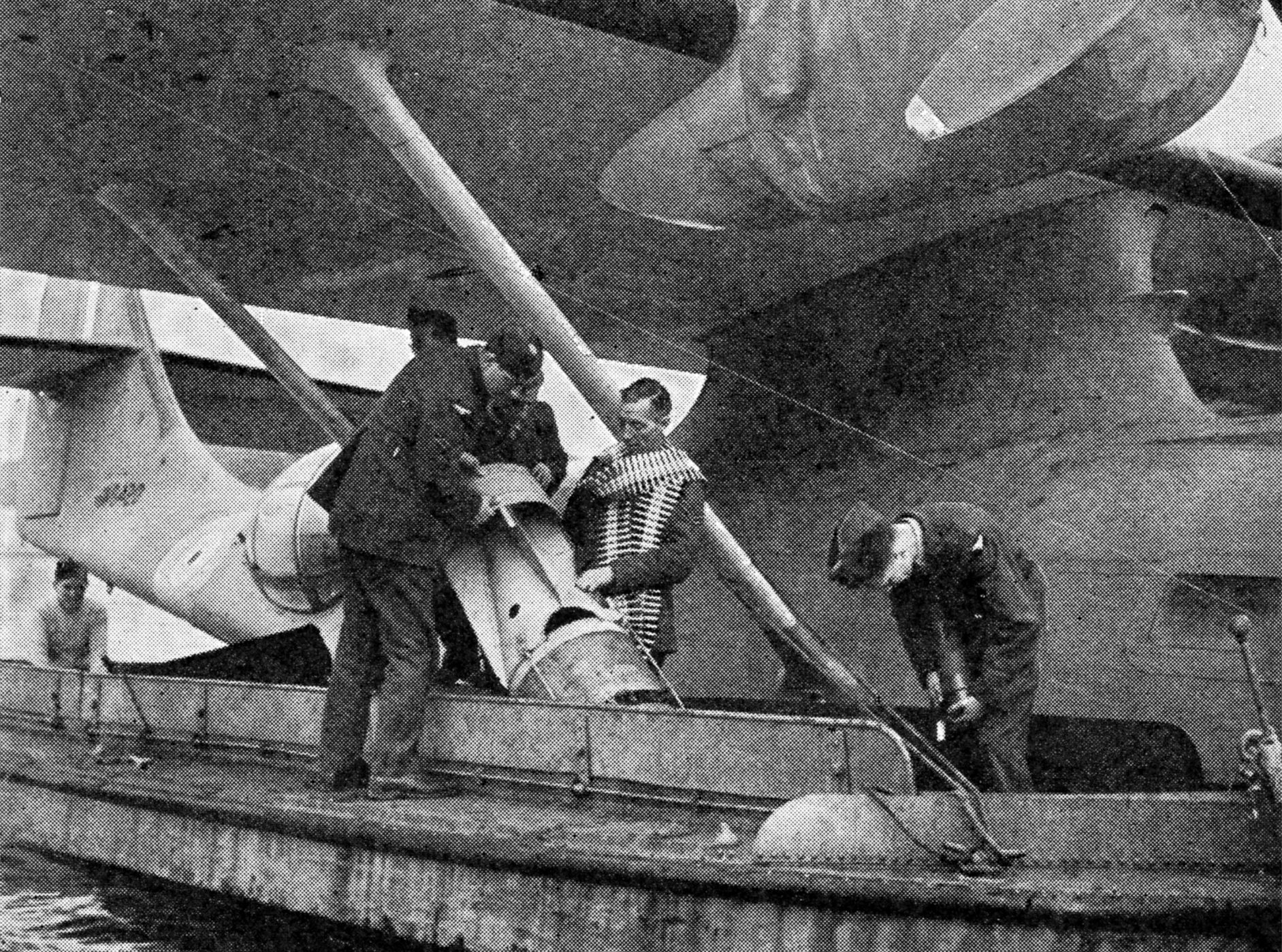
LOADING
UP A CATALINA
The
long range Catalina seen above will soon be setting out on an ocean
reconnaissance. Alongside is a launch which has brought ammunition for
her guns and anti-submarine bombs. The latter will be hoisted into bomb
racks situated beneath her wings ready for instant use should an enemy
submarine be rash enough to show its periscope above the surface
Aircraft
of the Command made 305 attacks on U-boats, nearly all of them in the
course of the Battle of the Atlantic. They destroyed seventy-five enemy
aircraft actually approaching to molest convoys, and drove off more
than 500 of them, often heavily damaged. Today Coastal Command has an
area of five and a half million square miles of sea to
patrol. Many pilots who are serving with the Command have a
total
of much more than two thousand operational flying hours to their credit
in their log-books.
Perhaps
the most astonishing feat in the Battle of the Atlantic was the
surrender of a German U-boat to Coastal Command aircraft. The U-boat
was sighted by a Hudson on its routine patrol and was forced to the
surface by bombs.
THE HUDSON ATTACKS
Almost
immediately the whole crew started to pour out of the conning tower,
probably in an effort to man the guns, but the Hudson immediately
attacked them with machine gun fire, and after four such attacks the
U-boat crew surrendered, waving a white shirt and a piece of white
board to make their intention clear. The Hudson continued to circle the
U-boat with guns trained to resume the attack if necessary, while
signals were sent off' to base to bring other aircraft to the relief,
and surface vessels to take charge of the U-boat.
After three
and a half hours a Catalina arrived to take over from the Hudson. She
stood jailer in the air for a further seven and a half hours before the
first naval vessel could get to the scene. In spite of a heavy gale that
was running, the Navy got the U-boat crew off and brought the U-boat
intact into port. Coastal Command aircraft kept up air escort for a
further forty hours until this was accomplished. This was the first
under-water craft ever to have surrendered to an aircraft (Fig. 13).
Once a Coastal Command flying boat was forced to land in the middle of
the Atlantic at the height of a gale and remained afloat for seven hours
before being reached by a surface vessel. On more than one occasion
flying boats have landed alongside torpedoed seamen, drifting exhausted
far away from land, and have brought them safely home.

U-BOAT
SURRENDERS TO A HUDSON
Fig. 13.
The U-boat above, as explained in the text, was forced to surrender by
a Coastal Command Hudson, which called up naval forces in order to
secure the prize. The U-boat was afterwards brought into port intact.
This was the first submarine ever to surrender to an aircraft, but since
then pilots attached to squadrons of Coastal Command have brought quite
a number of German U-boats to the surface by dropping depth charges or
bombs
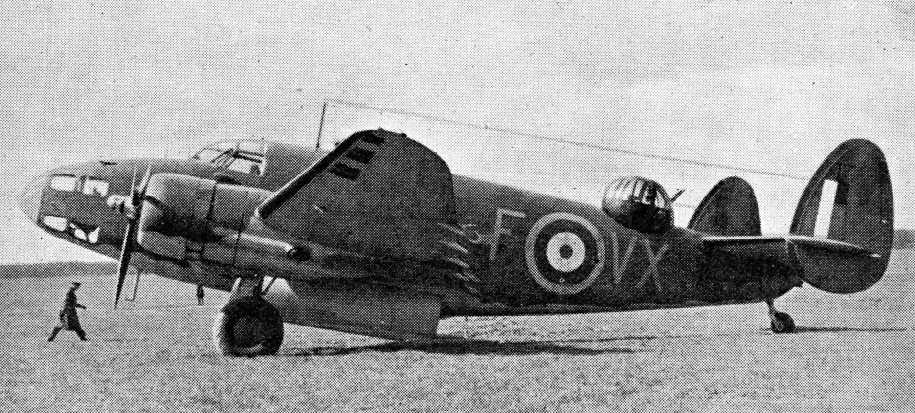
LOCKHEED
HUDSON RECONNAISSANCE BOMBER
Designed
and built in the United States, the Hudson has done valuable service
with Coastal Command. It has a wing span of 65 feet 6 inches and a
length of 44 feet 4 inches, and is armed with four machine guns, two in
the nose, two in a turret on top of the fuselage
The
aircraft of Bomber Command have their objective to bomb, their definite
task assigned to them, and then their sortie is over. Aircraft of
Fighter Command have short flights of extreme skill and hazard, packed
with excitement, and then they land, but the average sortie of a
Coastal Command Catalina, for instance, lasts for eighteen hours.
Sometimes they fly for a complete day and night. One Catalina returning
to its base at night found the weather unfavourable for alighting, so
it flew back to sea and stayed there until daybreak when it
could
come down in comfort and safety.
DAY AND NIGHT PATROLS
These
flights are conducted day by day and night by night far out over the
sea. For the most part they are not spectacular but they are invariably
gruelling, wearying, a supreme test of airmanship, and a tremendous
physical strain. That is typical of most Coastal Command flights either
in flying boats or in land aircraft.
A cross section of the
Coastal Command aircraft actually in the air on any one day would
provide as magnificent a variety of flying as any in the war. Up beyond
the Arctic Circle there would be perhaps a long range Hudson traversing
the ice-packs, flying around the towering masses of an iceberg or
skimming the desolate mountains of Greenland. South of that rules the
Atlantic, and here Coastal Command aircraft gather thickly. Many of
them are circling round and round the ocean convoys—Catalinas,
Liberators, Hudsons. Closer in roam the long range fighters,
particularly the Beaufighters which are in themselves a romance of the
air war. They are the latest and most modern of the long range fighters
of Britain. Some of them, manned by Coastal Command personnel, were
sent down to Malta when the order went out that the convoys must get
through: and get through the convoys did. One force of Beaufighters down
there shot up thirty-six enemy aircraft in Sicily without loss to
themselves, in one hour. No less striking has been their record over
waters nearer home. The first Beaufighter that ever went out over the
Atlantic met a Focke-Wulf Kurier within the first two hours of its
flight. The pilot got the huge enemy raider into his sights and pressed
the gun button. Before he had time to take his finger off the button
again the Kurier was falling to pieces in the air in front of him.
To
continue the picture of Coastal Command aircraft in the air on any
single day: over the Atlantic and around Iceland, the hunt for the
U-boats is proceeding for mile after mile over the dull sea. Coastal
Command aircraft are flying on pre-determined routes, with every member
of the crew staring fixedly at the sea. Once in a while the conning
tower or the periscope of a U-boat is sighted, and, with a swift dive,
down go the bombs. That part of the picture can be repeated all over
the eastern Atlantic, from the north-west approaches far down in the
Bay of Biscay; from the Bay of Biscay farther south still off the
European land masses to Gibraltar; and from Gibraltar still farther to
the south off the west coast of Africa where the Coastal Command
aircraft still relentlessly pursue the U-boats and still guard the
convoys.
But on this one day we have picked out—on
any day—the real concentration of Coastal Command aircraft will be over
those waters that surround the British Isles and stretch to the coast
that the enemy has occupied. Beaufighters are scouring the North Sea;
Beauforts, in little flights of three, are dodging up and down the
Norwegian Fjords and skimming round the islands where the Nazi shipping
lurks.
There are Hudsons along the Danish coast and Hudsons
flying farther south still, past the Friesian Islands and into the
Heligoland Bight, off Holland maybe Hudsons or Beauforts will attack
the enemy shipping, and farther westward at the same time there would
be Hudsons, Blenheim fighters or perhaps even an Anson or two searching
over the mine-fields for some dinghy that may contain the crew of a
bomber which crashed after last night’s raid on Germany.
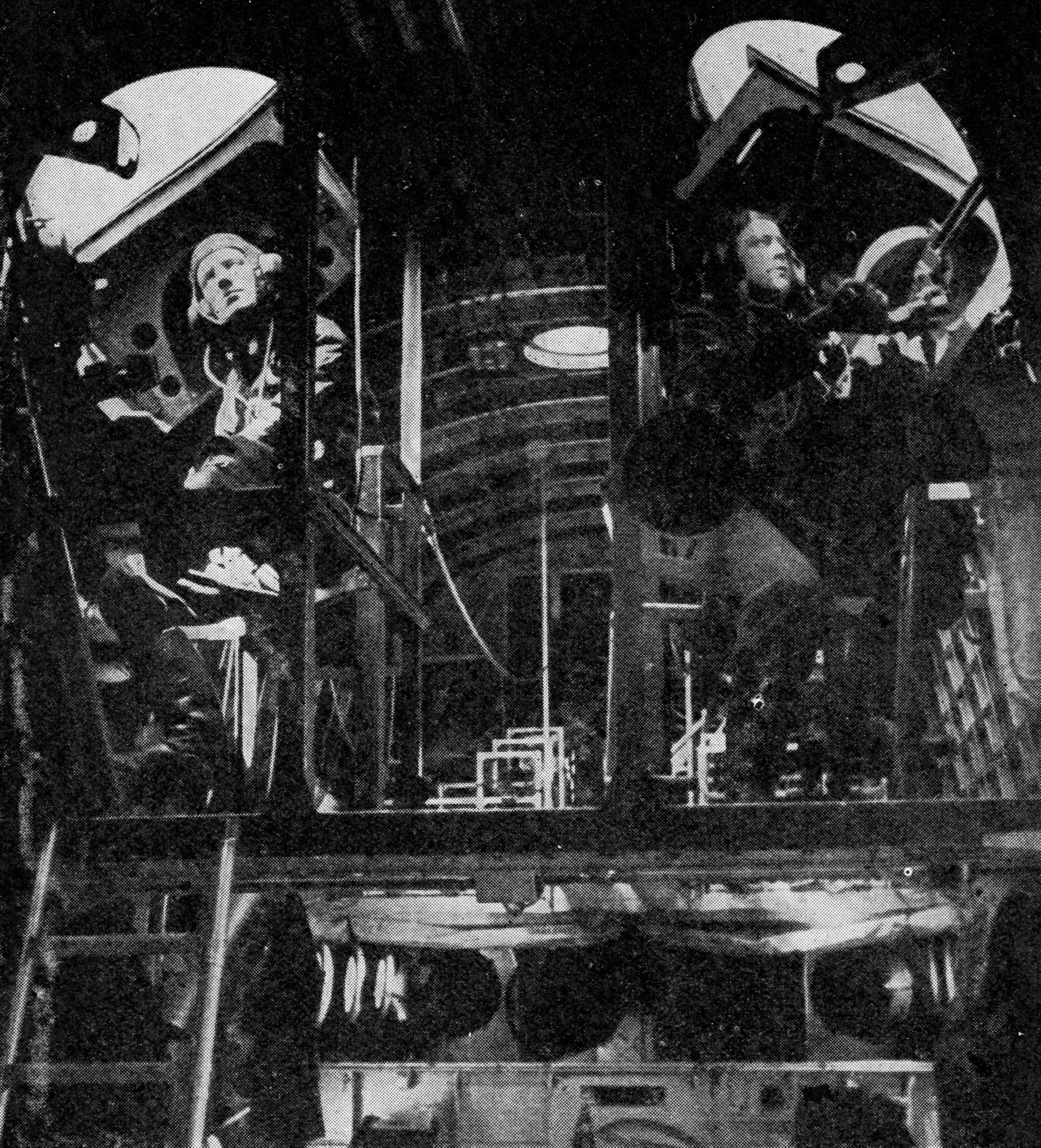
SUNDERLAND
GUNNERS MAN THEIR GUNS
The
Short Sunderland flying boat is sometimes called the “Flying Porcupine”
because it bristles with guns. In addition to power operated turrets in
nose and tail there are two gun positions amidships, illustrated above,
which command a very wide field of fire
WATCHDOGS OF THE CHANNEL
All
down through the English Channel it would be difficult to miss the
aircraft on reconnaissance nosing into the harbours, slipping along the
coasts, photographing, reporting back. There will be a
Beaufort or
two searching the Channel Islands, while farther out to the west will
fly the Sunderlands, the Catalinas, the Liberators, the
Halifaxes,
the Wellingtons and the Hudsons, guarding yet more of England’s
precious merchant shipping.
You will certainly find Coastal
Command aircraft somewhere along the Brittany coast and far out into
the Bay of Biscay. The flying boats may be taking down to Gibraltar, and
so out to the Middle East, some generals or some important Government
officials. Coastal Command men are in the Far East. And as a fringe to
all this scene are the photographic reconnaissance aircraft whose
boundaries are set wider still, far over Europe to the North Sea or
down to the Mediterranean in the south.
THE BREAD AND BUTTER BATTLE
There
is no exaggeration about that picture, a typical day’s flying of Coastal
Command. It happens every day, and it continues throughout every night.
A man could almost count on his fingers the number of hours since the
start of the war when there have been no Coastal Command aircraft flying
anywhere. And all this has grown from the handful of aircraft and the
small fleet of flying boats with which Coastal Command began the war. It
started almost as an ancillary command, but from the first day of the
war it forced recognition that it was an essential army of Britain. Now
it has grown into a huge force covering a greater area, as a single
Command, than any other complete air force in the World, including the
Luftwaffe. It fights a battle on a gigantic scale over a huge area, and
it fights essentially the “bread and butter” battle of Britain, for if
the battle of the ocean is lost and supplies cannot get through, then
indeed all is lost. But there is not one scrap of evidence to show that
that battle will be lost, and a Coastal Command grown as strong as it
stands today is the best guarantee of that victory.
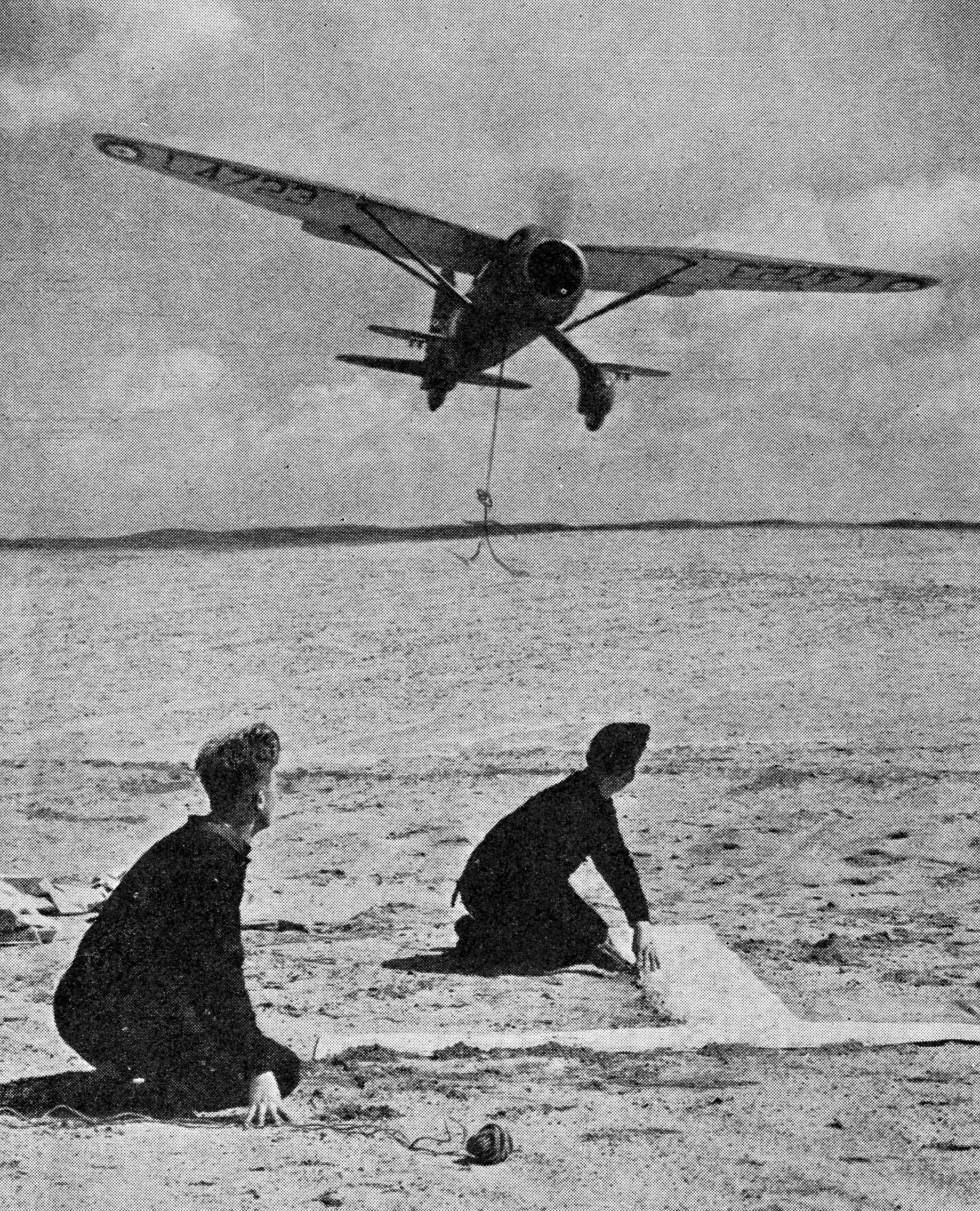
HOW
THEY USED TO DO IT
In
the early days of Army Co-operation, before the intense development of
wireless communication, Lysanders were used to pick up messages from
troops in forward positions. The hook suspended from the fuselage of
the above machine was used for this purpose and the “T” of white cloth
spread out on the ground immediately below was so placed to show the
direction of the wind
CHAPTER
9
Army
Co-operation Command
Lessons
of this war. Need for air “umbrella.” Lysanders outdated. Fast fighters
for reconnaissance. The Mustang. Army officers seconded to the Command.
R.A.F. pilots have to be military “encyclopedias.” New intelligence
systems. Paratroops and airborne troops
THE question of
the relationship between air and ground forces has always been
a
matter of controversy. From the days when the possibilities of the use
of an air arm in warfare were first visualized, there has been argument
as to whether an air force should be merely part of the army under
direct army control, or whether it should be a separate concern with
its own individual organization and authority and power to operate in
its own way.
IMPORTANCE OF AIR COVER
The
lessons of the present war have definitely proved that without air cover
the success of any army operation is endangered. From that fact a clear
understanding of the position of the air arm is now developing. The use
the Germans made of air power when they marched into Poland, to Norway
and then through the Low Countries into France first suggested the
ultimate solution though in no case did they meet with stiff air
opposition. More lessons were learned as a result of the war in Greece
and the airborne invasion of Crete. Finally, they were put to test and
clarified by practical experience in the Egypt and Libya campaigns which
began with the defeat of Rommel at El Alamein and continued with his
chase across fifteen hundred miles of African desert into Tunisia. Air
power, the Royal Air Force, showed itself as the protective cover and
advanced striking arm of the Army, its “fourth dimension,” working as
an organization of its own but carrying out operations as an integral
part of the high command controlling the whole campaign. It became the
eyes and ears of the army, its long range artillery reaching where no
guns could reach; its fighters were the army’s guerillas and its entire
organization was the handmaid of the land force.
But the path to
that state had not been easy. It had meant experiment and trial,
tribulation and error. It had meant the scrapping of many pre-conceived
ideas and the formation within the Royal Air Force of an entirely new
command, Army Co-Operation Command, which was to spend two years of
unsung and unpublicized effort in the intensive training of personnel
in a new technique.
NEW PLANES
It
had also meant the complete re-equipment with several new types of
aircraft; the provision, for instance, of fast single-seat and well
armoured fighters in place of the old and slow Lysanders which it was
thought at the beginning of the war would do all that was necessary in
the way of army reconnaissance. Light bombers and dive bombers had to
be found and carriers for paratroops, as well as gliders and the
aircraft to tow them.
The
first use of the air to give help and
assistance to a land force saw the employment of spherical balloons and
man lifting kites. Both were used successfully in the Boer
War.
Then airships, now obsolete, took the place of balloons. When the war
of 1914 began, the first British aeroplanes to go to France were
intended solely for reconnaissance for the army. Everybody knows that
they were cumbersome, “bundles of wood and string,” to quote a pilot of
those days. They did not carry bombs. Armament was
also non-existent, except for the personal choice of some
pilots
and observers who took revolvers and even shot-guns up in the air with
them. But they did a job. They gathered information from behind the
enemy lines, even if they never flew very far. Height gave pilots and
observers the power to see things that the army commanders and
artillery dearly wanted to know about.
It
was as though the vantage point that is the dream of every army
general, an overlooking hill, had become fact whether he fought in the
middle of a flat plain or not. Air power had become vital to the land
force. But not just to one force. It was vital to both sides. Both
tried to use it and both tried to prevent its use. There was only one
thing to be done. An aircraft high in the sky could only be reached by
another aircraft, one that was armed to shoot it down. Fighters came
into existence and, as under the impetus of war the aeroplane developed
rapidly and became a weight carrier, the bomber also arrived. The two
arms of the R.A.F. as we knew them when this war began came into
existence.
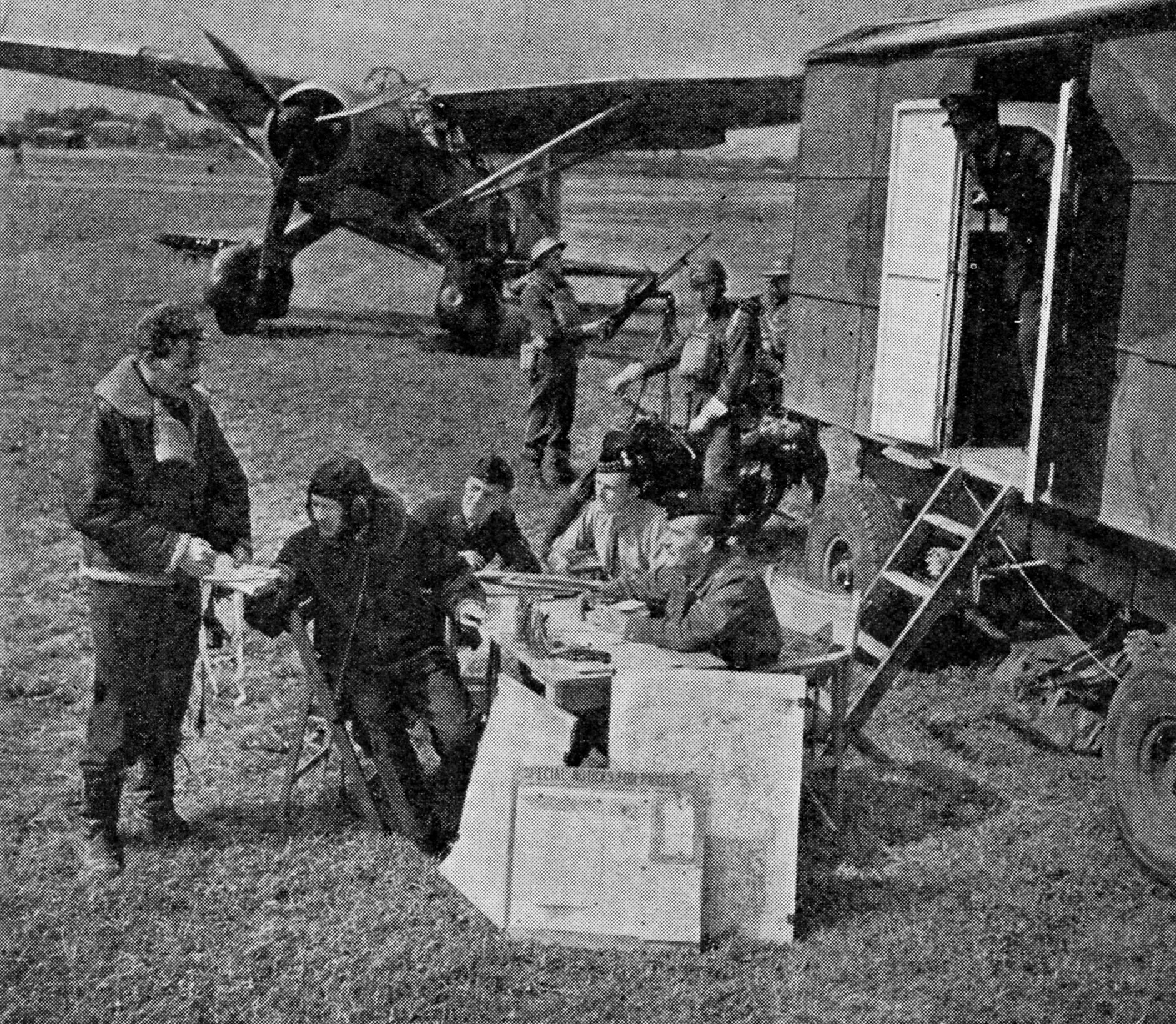
MOBILE
HEADQUARTERS
Mustangs
have now replaced the Lysander above whose pilot has just returned from
a reconnaissance flight and is reporting it to the air liaison oflicer. A
despatch rider stands by and a machine gunner keeps a look-out for
enemy aircraft. The mobile headquarters on the right is equipped with
wireless by means of which it keeps in touch with aircraft while on
patrol
INTERPRETATION
STAFF AT WORK
An
army co-op. aircraft has returned from a photographic reconnaissance
and the prints are now in the hands of the interpretation staff. With
the aid of stereoscopic and other viewing devices they are
able to
gather valuable and highly accurate information regarding the
disposition of enemy troops upon which the army commander will base his
future plan of campaign
The fighter, originally purely intended to see that an
enemy machine did not reconnoitre or at any rate get back home with the
results of its observation, became the means of securing
domination of the skies. The bomber, originally intended as a
reconnaissance machine and then as something capable
of dropping a
“shell” in the places just beyond range of the army’s guns, became an
offensive weapon capable of interfering with enemy production deep in
the interior. Each seemed to be a natural complement to the other and
make a whole that ought to work independently of the land forces, be a
separate service complete in itself, as distinct from the army as the
navy and only co-operating as a separate service. This theory was
accepted. The army lost its Royal Flying Corps and the navy its Royal
Naval Air Service. They were joined together as the Royal Air Force.
The army lost direct control of its eyes and ears.
When this war
began, that position, so far as the army and the R.A.F. was concerned,
remained, though the Navy had managed to re-establish its Fleet Air
Arm, and Coastal Command of the R.A.F. had become a close worker with
the Admiralty. The R.A.F. had fighters and bombers which were as modern
as the times, but it had few aircraft specially designed for army
reconnaissance work and little conception of what that reconnaissance
would mean. Both the army and the R.A.F. had also been severely
handicapped by pre-war disarmament efforts, one of the effects of which
had been for the R.A.F. to conserve what resources it had for R.A.F.
purposes pure and simple, the development of its fighters and bombers.
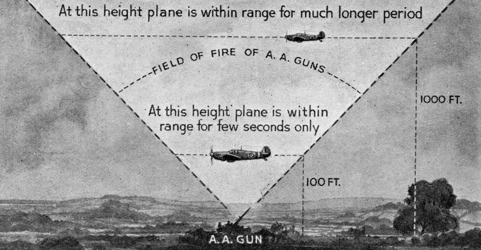
WHY
A LOW FLYING PLANE IS DIFFICULT TO HIT
Fig. 1.
As shown above, an aircraft flying at 100 feet or less is an extremely
difficult target to hit because it remains within the effective arc of
fire of the guns for such a very short time
ARMY RECONNAISSANCE
The
aircraft that were available for army reconnaissance were of a type
that needed certain conditions in order to operate successfully. They
had to have freedom of leisurely movement in the air. A low flying plane
is hard to hit (Fig. 1). They must be protected by their own fighters or
be left entirely alone by the enemy. Neither was possible. The first
because the R.A.F. had not got enough fighters and the second for the
reason that the enemy was not charitably minded.
Speed of the
fighter type of aircraft was not considered necessary for army
reconnaissance work and the machines used were designed to ensure that
the pilot had a good view. They were Lysanders and, for longer range
work deep into enemy territory, Blenheims. Aircraft that could act as
the army’s primary attacking force, light bombers and fighter bombers
were not available. Nor was there a sufficiency of fighters. It was not
even expected that the Germans would decide to use aircraft in that
particular way.
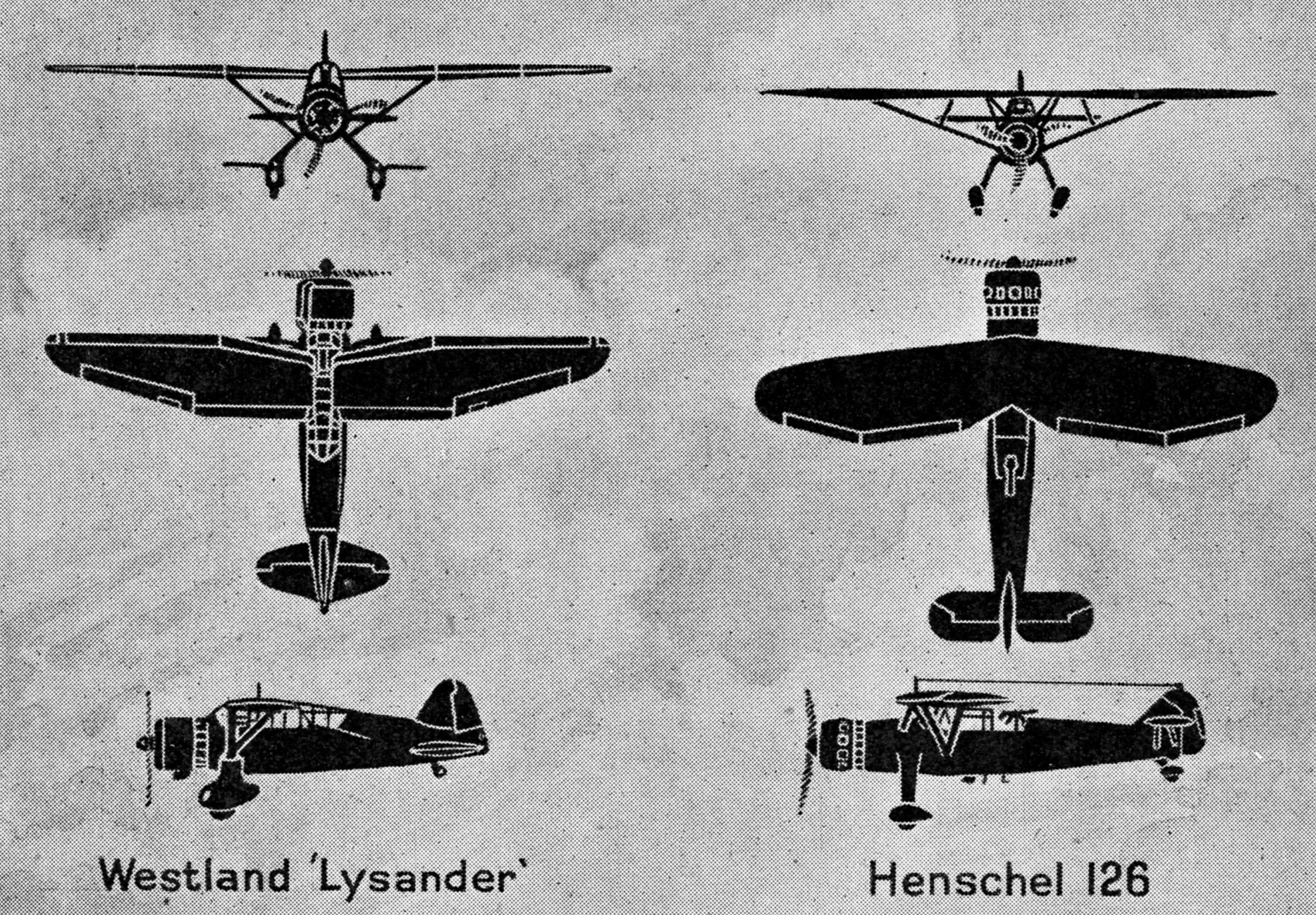
HENSCHEL 126
But
the Germans had also designed a slow aircraft specially for army
reconnaissance work and had produced the Henschel 126, a machine almost
identical with the British Lysander (Fig. 2).
Then came the
Battle of France to emphasize the tactics the Germans had used in
Poland, Norway and the Low Countries and show that, given air
superiority, the dive bomber could be a potent weapon. The Battle of
France ended with the withdrawal of the British troops, but a great and
important new principle of warfare had been established. It had been
made clear that the success or failure of an army depended on the
amount of air cover it could command. It was realized that, with fighter
cover, land forces had freedom of action, reconnaissance planes could
work unmolested and the dive bomber did have a use.
LYSANDER
AND HENSCHEL 126 COMPARED
Fig. 2.
The main difference lies in the shapes of the wings, which are very
distinctive, the Lysander having a straight leading edge and the
Henschel’s being swept back. Note also the distinctive shapes and
positions of tailplanes and the extra struts of the Henschel
In France
the Germans had many times the number of aircraft at the disposal of
the British. The German staff was able, consequently to plan every
phase of its swift advance with the knowledge that its own troops would
be practically immune from air attack and that the Luftwaffe
would
be delivering concentrated attacks behind the British lines on
communications, reserves and dumps. The Germans were able to plan their
bombing attacks in the sure knowledge that their tanks and troops would
reach certain positions at specified times. They worked out a detailed
time-table which took into account their air movements as well as their
land movements. They subordinated everything to this precise
co-operation with a result that is now history. They showed the world
how air and land forces could, and must, work together, and Britain
took heed. Britain formed Army Co-Operation Command within the R.A.F.
to put into effect the lessons learned and give the land forces back
their air arm. The idea of the relationship between air and land forces
had gone almost full circle. The experience of Libya showed later that
the Germans can be beaten at their own game—and beaten hard.
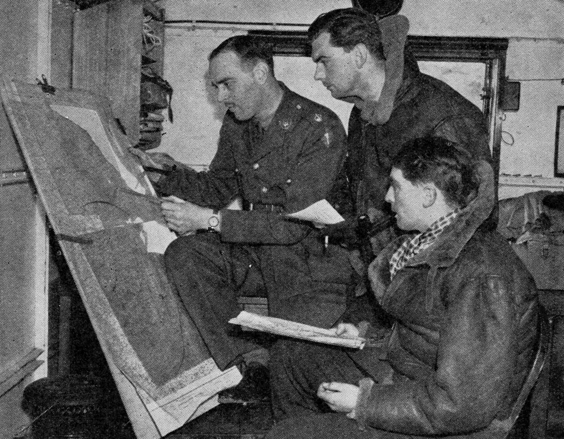
BRIEFING
MUSTANG PILOTS
The
pilots seen above are just off on a reconnaissance. The air
intelligence liaison officer explains the purpose of the flight, the
area to be reconnoitred, and what is to be looked for
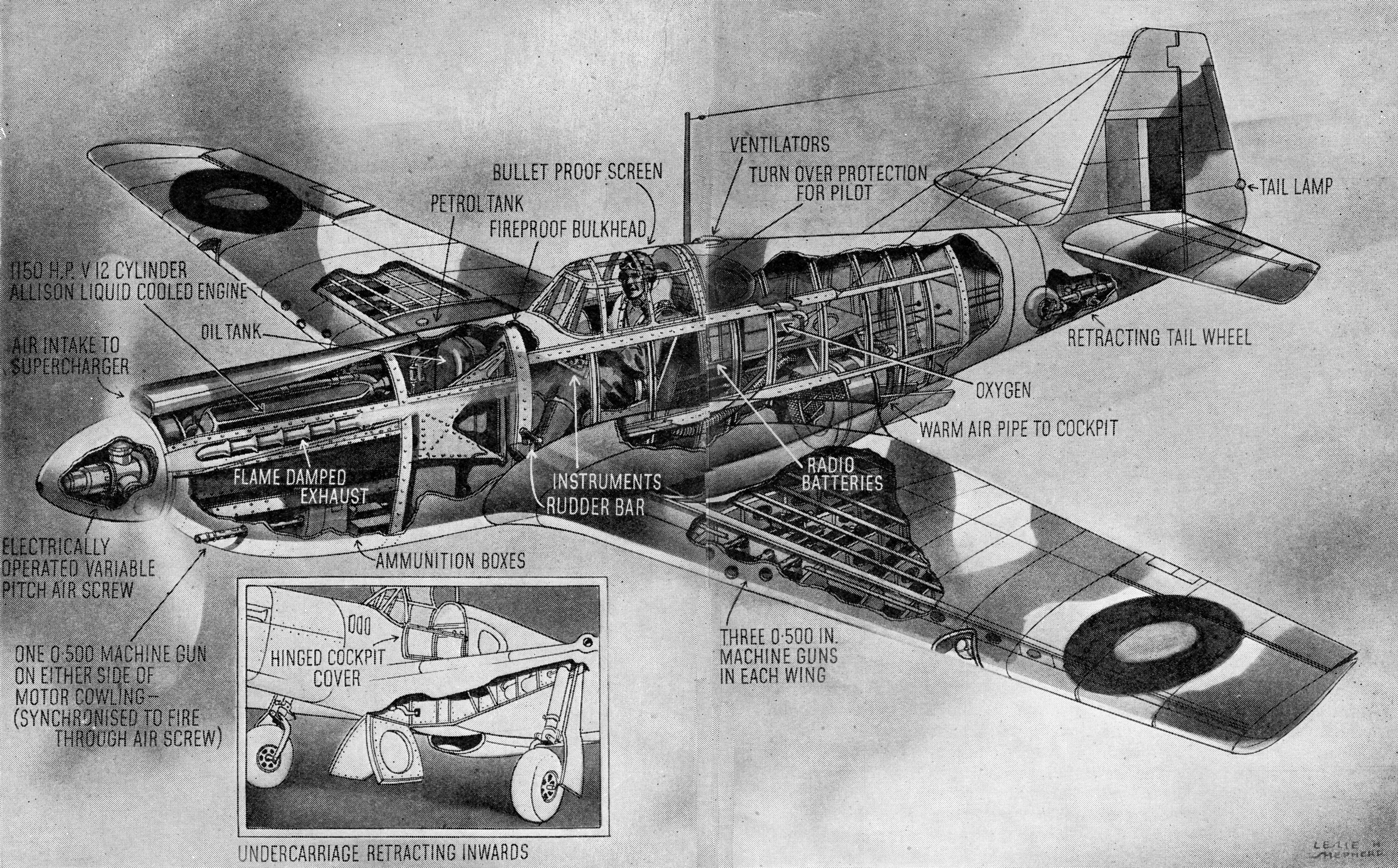
DETAILS
OF THE LONG RANGE MUSTANG
Fig. 3.
The Mustang is a fast single-seater fighter in service with the Army
Co-operation Command of the R.A.F. Though it is American-built it is of
British design and has a maximum speed of about 370 miles per hour at
15,000 feet. This aircraft is also much used for reconnaissance work as
well as for light bombing, and it specializes in low level attack. Its
armament consists of two 0.5 machine guns in the fuselage and three
other machine guns in each wing. It is powered by an 1,150 h.p. Allison
liquid cooled 12-cylinder “V” type engine. The dimensions of the
Mustang are: wing span, 37 feet, length, 32 feet 2 inches; height, 11
feet 8 inches. The wing-tips are similar to those of a Grumman Martlet
SPOTTING FOR THE ARMY
The
first step taken by Army Co-operation Command was to discard the
Lysander and re-arm with fast, well-armoured aircraft. The American
Tomahawk was used, then the Kittyhawk and later on the powerful Mustang
(Fig. 3). In addition to these faster types of planes the Taylorcraft
Auster is also used. Paratroops came into existence. Airborne regiments
using gliders were formed. Light bombers suitable for the peculiar
needs of the army were produced and pilots were trained in their
special use. Fighter bombers were developed for army purposes. Regular
army officers were seconded to the R.A.F. to work operationally
in
the Command. R.A.F. men were trained in that mass of knowledge which is
vital to the army, since they would be required to supply military
information. Pilots had to learn to identify the mark of a German tank,
recognize the differences in the types of guns moving along a road and
know how to draw the correct inference from a column of motor cyclists
with side cars as against a string of motor cyclists. It was not enough
that an Army Co-operation pilot could fly. He had to have a thorough
knowledge of the German army, its equipment and how it
was transported, and of its armoured formations. The pilot had
to
be something of a military encyclopedia as well as a highly skilled
airman.
THE LIAISON SECTION
For
this reason there are no R.A.F. Intelligence Officers on the staff of
the Command. The intelligence brought back is not of an Air Force
nature. It is military information. Each Army Co-operation squadron
accordingly works with a small liaison section of three army officers
who have been specially trained. They are picked men. It is their duty
to brief pilots, advise them on their tasks and extract every
scrap of military information when they return.
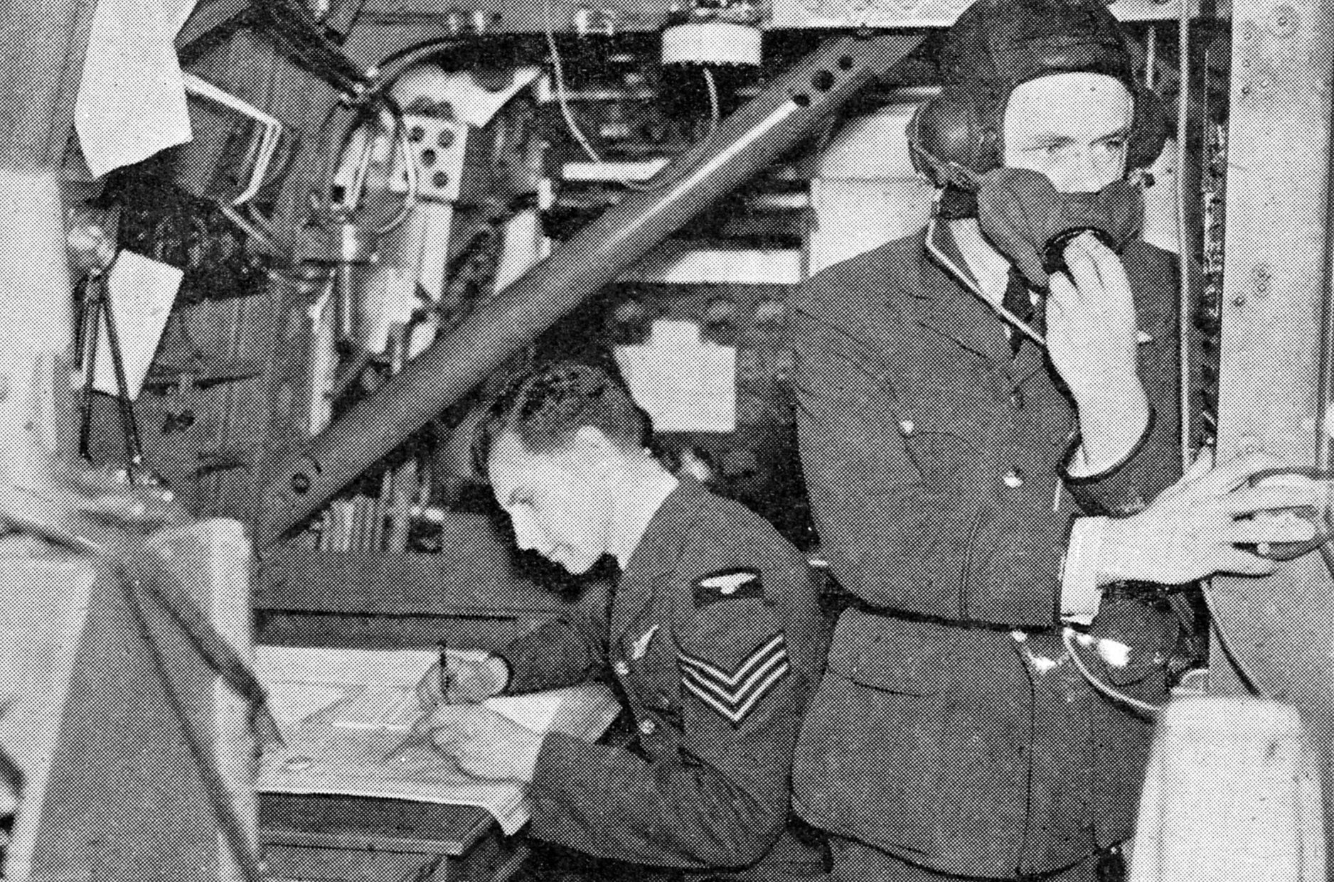
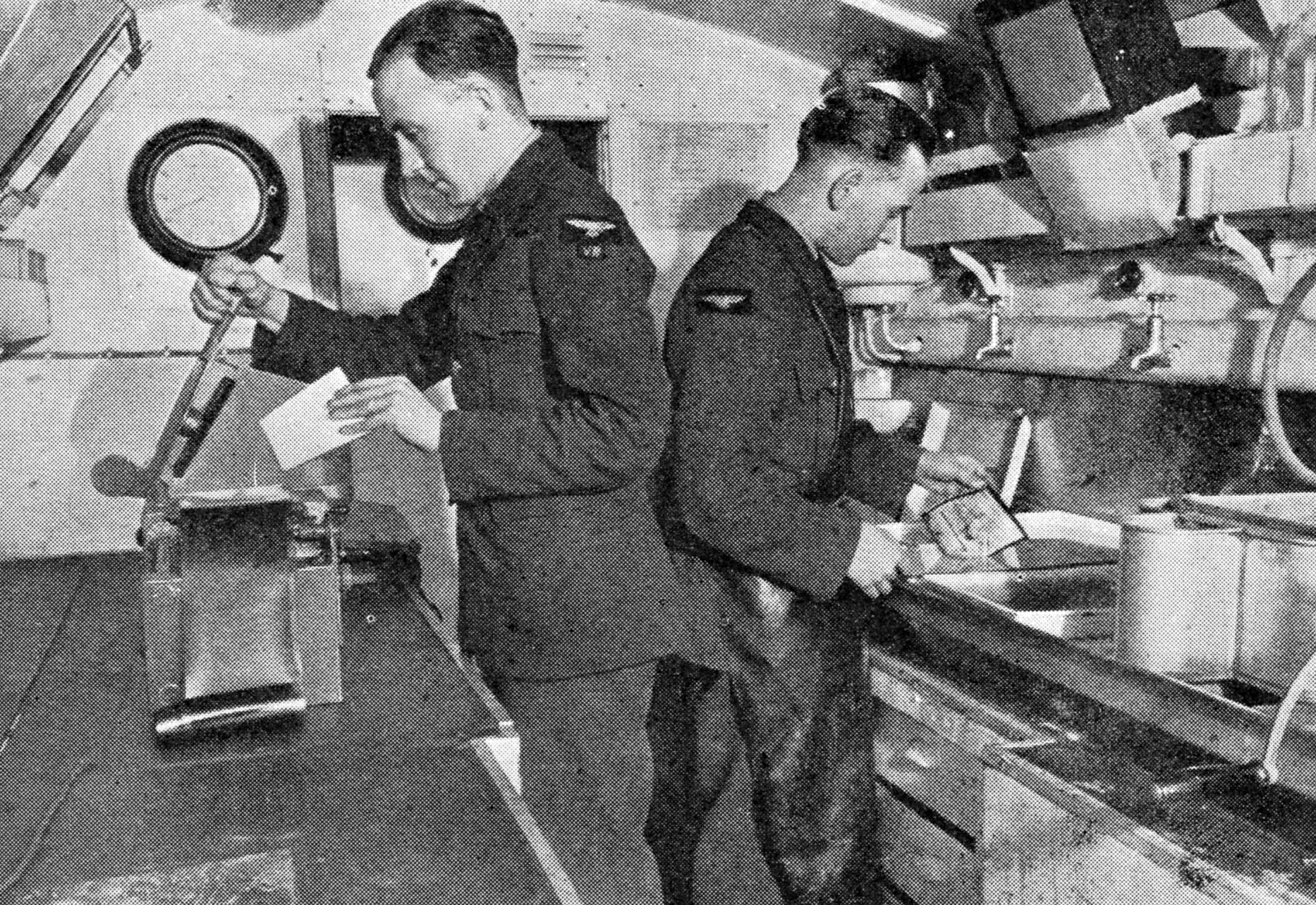
Each of these
sections has its own travelling photographic tender where the results
of each sortie are processed. To the army liaison officer falls the
task of making the first interpretation of the pictures brought back.
This interpretation, along with the verbal report of the pilot, is
telephoned or wirelessed or sent by dispatch rider to headquarters.
Army
Co-operation pilots pass through the usual flying schools of the R.A.F.
But to this is added a course in the art of military manoeuvre. This,
in time, leads them to the specialized training of Army Co-operation
headquarters under which also come special training units to instruct
airborne troops, parachute organizations.
Much has happened
within the Command, apart from the training of pilots to support the
army in the Middle East. Pilots have been taught how to give support
over here, on the Continent or wherever else they may be needed. For
months they trained on their Tomahawks and then on their Mustangs.
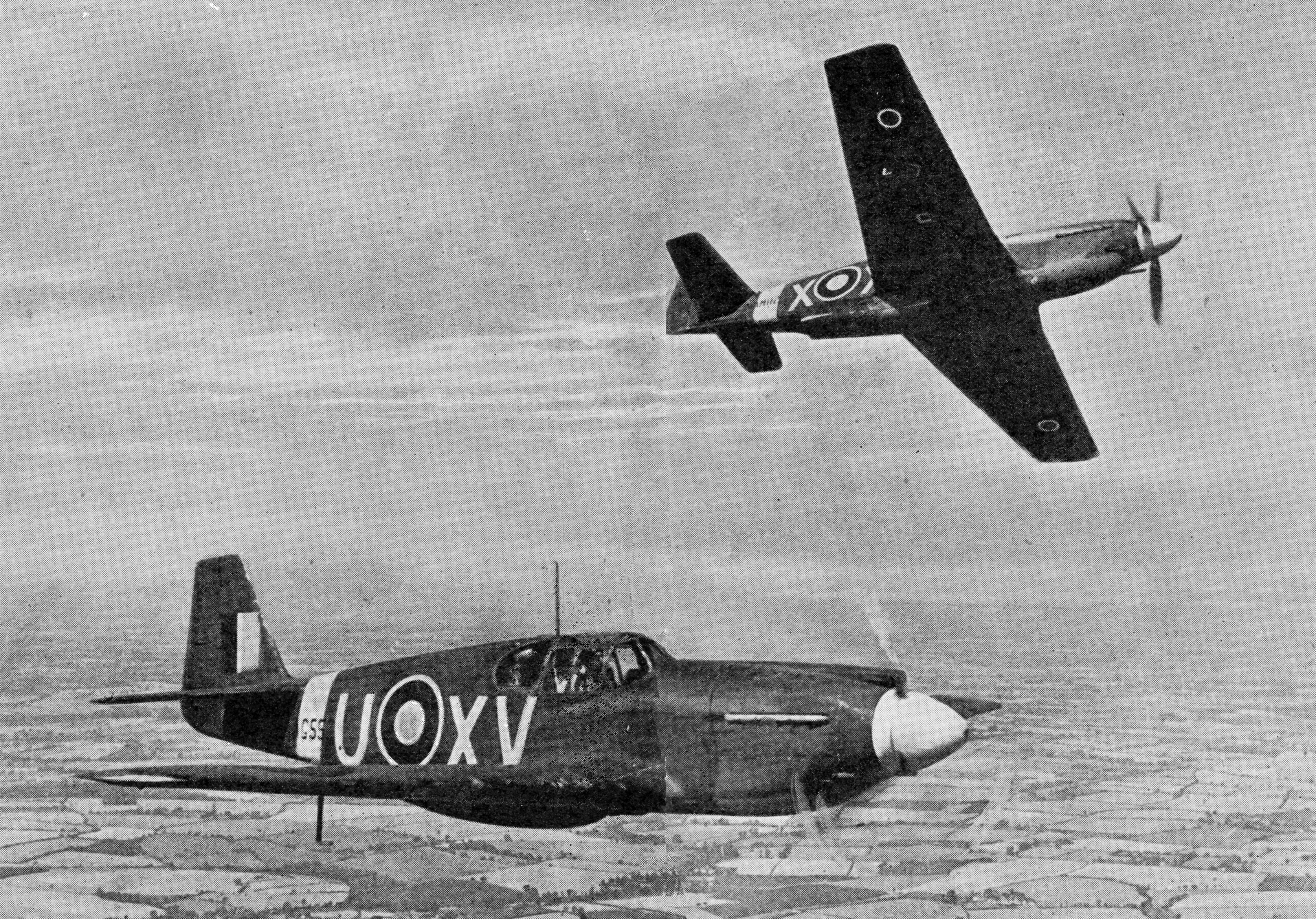
MUSTANGS
OF ARMY CO-OPERATION COMMAND IN FLIGHT
These
fast Mustangs are the aircraft which do the work of army reconnaissance
behind the enemy lines. Apart from their high speed, they often fly so
low to take photographs that they return to base with evidences that
the tops of trees or telegraph wires have been flown through. Fitted
with special secret cameras, detailed photographs of small areas can be
taken at astonishing speeds. Frequently the pilot of a Mustang will
release the shutter of his camera at not more than 50 feet above the
ground while travelling at well over 300 miles per hour
The
change over from the old Lysander to the fast single seater fighter was
much greater than it looks on paper. It was a revolutionary change that
compelled the pilot to do the work previously done by a pilot and
observer. It compelled one man to do the thinking of two in a few
seconds instead of in minutes.
The British pilots got over the
difficulty with remarkable speed. The visual and photographic
reconnaissance carried out previouslyat a leisurely rate and at a fair
height had to be done at hundreds of miles an hour at tree-top height.
The pilots had to keep one eye on the ground, one in front of them, a
third behind them, a fourth above, a fifth to the right and a sixth to
the left. Careful training and the clever placing of a mirror gave them
visual powers equal to the imaginary six eyed man. In addition, the
pilot had to navigate his machine correctly, read his maps and make
pencil notes of everything of importance he saw below.
SUPPORTING THE TROOPS
While
undergoing this training the pilots mix with army personnel to gain as
much experience as possible of army methods. They take part in numerous
exercises and in due course carry out miniature sweeps across the
Channel to wreck Dutch, Belgian and French railways and canals. At
Dieppe, with conspicuous success, they played the part they had trained
for—that of army supporters.
The reconnaissance machine is
however only one side of the work of Army Co-op. Light bombers, of
which there are several squadrons, are piloted by crews specially
trained in the art of giving troops close support. Apart from machine
gunning and bombing advanced elements of the enemy, a task also carried
out by Hurricane bombers, they have another job of primary importance.
The laying of smoke screens or the dropping of smoke bombs to hide from
the enemy the activity of our troops on the ground, if not done
expertly, might cause the loss of a battle. The smoke is also a useful
agent in preventing the enemy from seeing the descent of paratroops.
AIRBORNE FORCES
All
glider pilots were at one time also trained by Army Co-operation,and
special aerodromes in the Command are set aside for making paratroops
air-conscious. The Russians were the first to develop the technique of
putting into action airborne troops, but the Germans followed their
lead rapidly and there is no doubt that the use of parachutists and men
in troop carrying aircraft played a large part in the
capture and
subsequent capitulation of Holland in the spring of 1940, and was
largely responsible for similar events in Crete a year later. Naturally
such modern developments have been by no means neglected by the Army
and the R.A.F.—witness the many successful landings of British
paratroops in Italy and elsewhere. Probably the most interesting aspect
of this system is that of the employment of parachutists, and
discussion on the subject with regard to both Britain’s and Germany’s
methods has been considerable.
The parachutist is a soldier by
rights and merely uses a formerly unusual means of descent in order to
pounce upon his enemy from unexpected directions. All necessary arms,
ammunition, explosives for sabotage, food and other supplies, even
bicycles, also parachute borne, accompany him on his descent.
His
training is not as difficult or alarming as it sounds; in fact the
wind is tempered to the shorn lamb to a remarkable degree.
Without
equipment he is invited to jump from comparatively low heights
increasing to something like ten feet on to a gymnasium mat. Partly
supported by a suitable tackle of ropes, pulleys and counterweights he
is then gradually acclimatized to some of the sensations of a real
parachute descent inside a hangar. Concurrent with these activities he
is subjected to a course of intensive physical training which attunes
him to an exceptional degree of physical fitness and when the time comes
for him to do his first real descent from an aircraft, he finds that
there
is if anything less cause for hesitation than when high diving for the
first time at a swimming pool.
A
disadvantage of parachutist descents is that arrival is roughly
equivalent to that following a jump off a ten-foot wall. Added to that
is lateral speed due to the wind. The process is apt to be painful, and
the parachutist is not always immediately possessed of the enthusiasm
necessary in a soldier about to undertake a hazardous operation.
Another point is that before he “takes silk,” as he calls it, he may
have spent many cramped hours in an aeroplane under conditions of great
cold and in darkness.
A typical aeroplane used by the R.A.F. to
transport parachutists is the Armstrong-Whitworth Whitley. These
twin-engined long range heavy bombers, suitably adapted for the
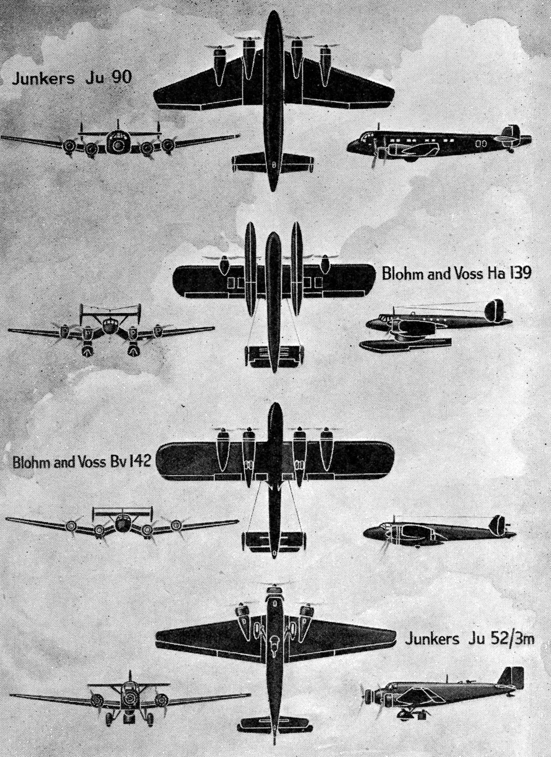
purpose, are shown in action in Fig. 4. Perhaps more mundane—if the
activity in which aircraft takes part can be so termed—is the method of
transporting personnel in multi-engined aircraft and disembarking them
in strategic positions actually on the ground. Typical British and
German troop carriers are illustrated in Figs. 5 and
6 for purposes of comparison.
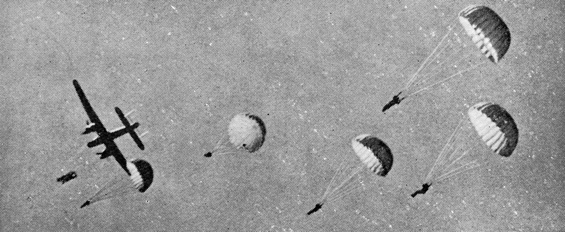
PARACHUTE
TROOPS BALE OUT
Fig. 4.
Parachute troops leaving Armstrong-Whitworth Whitleys during a
demonstration in England. The parachutes open immediately the men leave
the plane, making very low altitude jumps possible, thus reducing the
time of being exposed to possible sniping
Perhaps of all the methods of
transporting troops by air that in which towed gliders are employed
is most interesting. The gliders are towed one behind the other in
“trains,” as it were, each glider containing six or more fully equipped
infantrymen who, unlike parachutists, at first busily occupied with
preparatory measures, are already in parties under N.C.O.s ready to
begin instant hostilities with marshalled equipment on landing.
After
being disconnected from their parent craft gliders can reach their
objective in complete silence, their gliding range, moreover, may be
considerable, and they are released from a great height. Another
distinct advantage possessed by the glider is that it can land on its
skid with an extremely short run. It can thus avoid either real or
artificial obstacles in fields such as stooks, trenches, poles, wires,
and
so on.
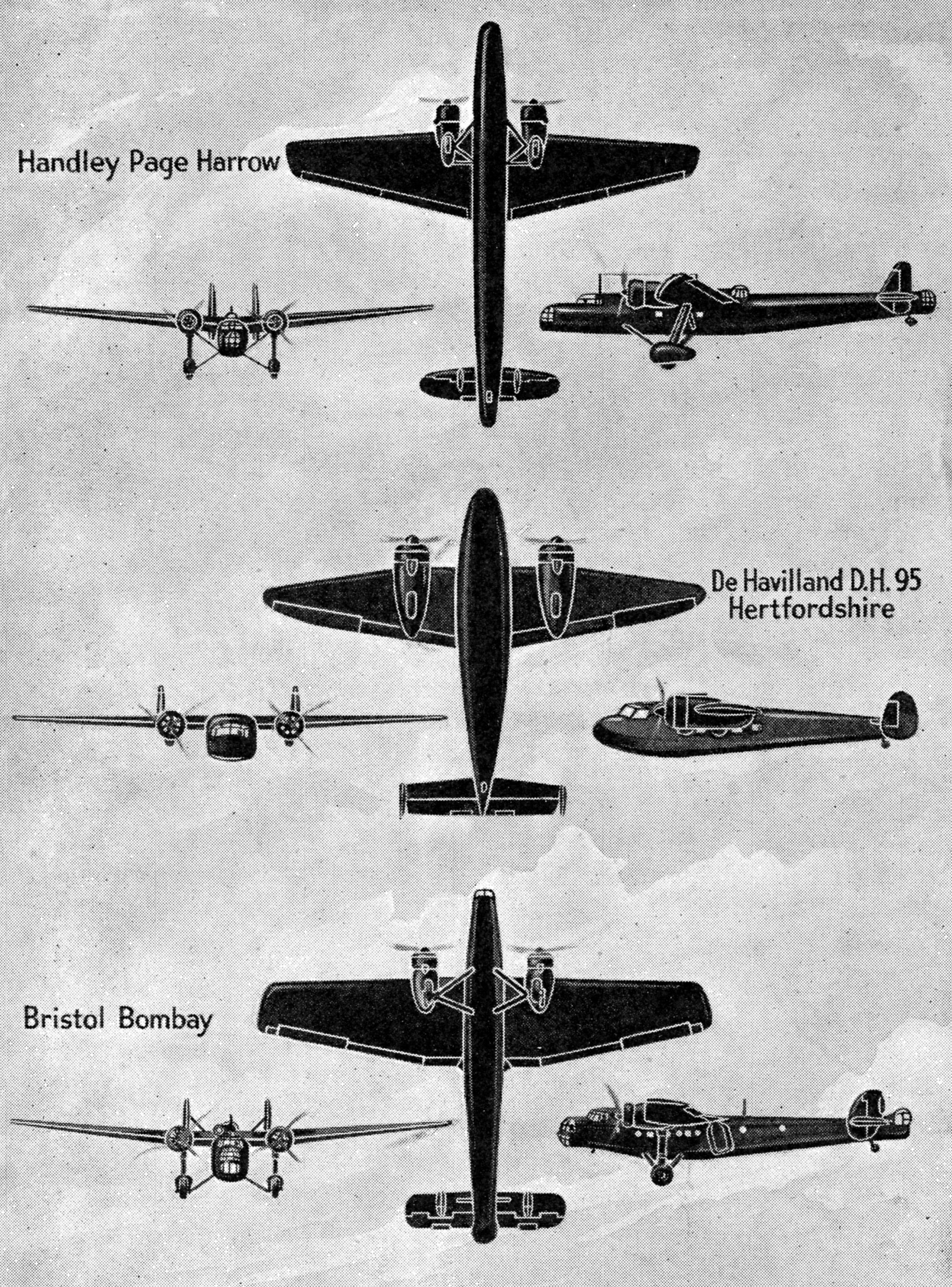
TROOP
TRANSPORT AIRCRAFT IN USE BY BRITAIN AND GERMANY
Figs.
5
(above) and 6
(below). Front, side and underneath views of some well-known British
and German troop carriers. The Harrow and Bombay are somewhat similar
in appearance, but can be distinguished by the fully tapered wings of
the former and the difference in the shape of the tailplanes. They each
have a range of about 2,000 miles. The Hertfordshire, the smallest of
the three, is the R.A.F. version of the Flamingo airliner. Its maximum
range is about 1,300 miles. Of the German types the best known is the
Ju 52. It can accommodate about fourteen
fully equipped parachutists and
has a range of about 1,000 miles. The Ju 90, formerly
a forty-passenger airliner, can carry a load
of nearly seven tons. The Blohm and Voss
142
is developed from
the long range seaplane, the Ha 139. Both have a range of 3,000
miles, but the 142 is considerably more powerful and faster by about 50
m.p.h.
How
many troops the largest practicable glider can
carry is still a matter of conjecture; suffice it to say that a
considerable force could be, and has been, landed by an enemy without
the
use of an inordinate number of towing aircraft. Should the latter
themselves be troop carriers, their effective capacity could be
enormously increased, depending upon the number and size of their
satellites, or if not troop carriers they could, as a sideline, carry a
useful load of bombs or a useful load of stores and equipment which
they could drop by parachute to the troops below.
It is too early to speak with any authority upon the question
of transporting
light tanks, ready for action, between the undercarriage legs of giant
aeroplanes, but it is known that both the Russians and the Germans have
carried out experiments in this direction.
It will be seen from
what has been written that the duties of an air force in
co-operation
with or support of an army are many. With the development of modern
warfare these will tend to increase rather than diminish. It is
comforting to know, however, that no matter how advanced the
prosecution of modern warfare may become, Britain’s Royal Air Force is
keeping abreast of the times in technical development, and is ready
with considerable alacrity to meet all the varied requirements of
Britain’s Army whatever they may be and in any
circumstances.
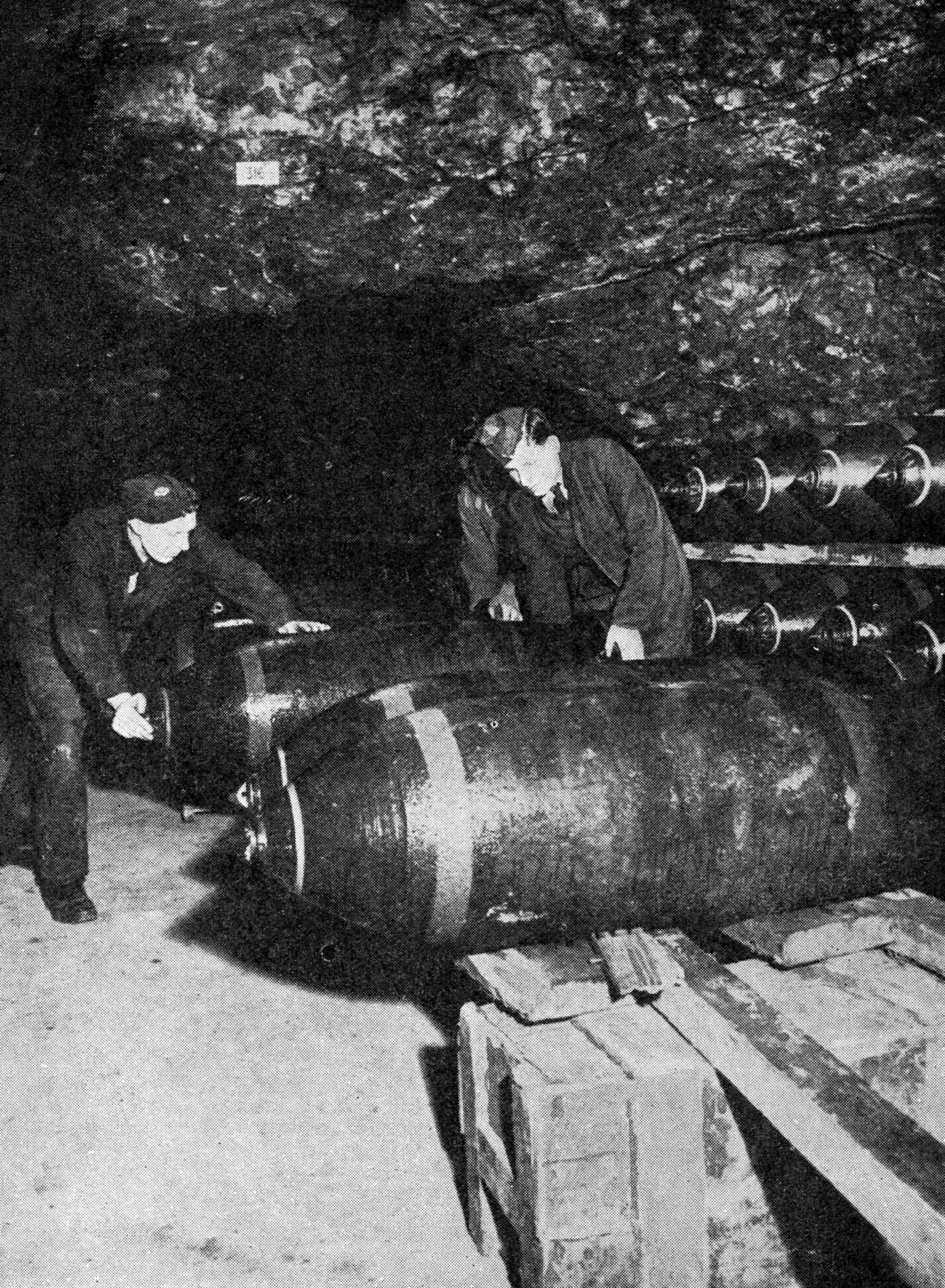
DISUSED
MINE BECOMES BOMB STORE
In
the galleries of a disused coal mine in Britain, hundreds of feet below
ground, are stored vast numbers of the various types of bombs which.
are being used by the R.A.F. to blast the war industries of the enemy.
Here is a store of thousand pound bombs such as are carried by our
heavy night bombers into the heart of Germany. Those above will soon be
on their way
CHAPTER
10
Maintenance
and Transport Commands
Three-quarters
of a million items in stock. Missing spare part can keep an
aircraft on the ground. Delivery by air if necessary. Football pools
helped. New machines flown to save ship space. Birth of the ferry idea.
Three routes across the Atlantic. World-wide service. Bombers bring
urgent munitions and mails. Flying boats from Bermuda
“GIVE
us the tools and we will finish the job” said Mr. Winston Churchill,
broadcasting in February, 1941. The same remark could be made by the
various Commands of the R.A.F. and the men about whom we have so far
been talking. Without the aircraft, the crews are useless and the
organization of the various headquarters so much waste effort. And,
behind the aircraft, a vast system of “supply-on-demand” of spare parts
is needed, airfields have to be constructed and maintained and
protected, and an enormous personnel built up and trained to see that
the operational units are always at the peak of efficiency.
BEHIND THE SCENES
It
is not within the scope of this book, nor is it possible in the space
available, to deal exhaustively with the subject. But no work on the
Royal Air Force is complete without some indication of the
behind-the-scenes work that goes on to put aircraft into the air and
see that they are maintained there. It is the little thing, the often
unconsidered trifle, that matters. The story of the clockmaker who was
called to the army in his registration group and then had to be sent
back to civilian life some weeks later because there was nobody left to
repair the alarm clocks on which workers relied to get to their factory
on time in the morning may not be exactly true, but it is typical.
Without him, production in the factory fell through lost hours. The
fall in production meant a shortage of a metal needed in aeroplane
construction. That meant, in the end, fewer aeroplanes and so it went
on. When the first assault forces landed on a beach near Algiers at dawn
when the North African campaign began, two R.A.F. Servicing Commando
Units went with them. They helped to capture Maison Blanche airfield
just in time to attend to the first Hurricane that landed there. Within
three minutes of that British fighter touching down it had been re-armed
and re-fuelled and was taking off again—to fight again.
Maintenance
Command of the R.A.F. has a raven as its badge, since it is the ravens
who “provide,” and it lives up to the full meaning of that one word. It
has a standing list of three-quarters of a million items
always in
stock and it is its proud boast that no aircraft is ever kept on the
ground for want of a bolt or a screw or a nut or a spare part, even if
that spare part is only in stock four hundred miles away. It will be
delivered speedily, by air if necessary, or a motor cyclist dispatch
rider will travel all through the night with it so that it is ready to
be fitted with the coming of dawn.
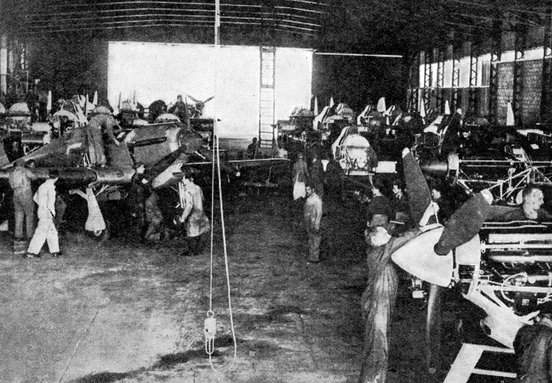
INSIDE
A REPAIR WORKSHOP
All
over Britain, the Middle East and elsewhere the R.A.F. has its own
emergency repair workshops, staffed by highly skilled mechanics and
fitters. In one of these workshops, pictured above, British fighter
aircraft undergo lightning repairs and overhaul for new operations
Manufacture
of aircraft is, of course, in the hands of the Ministry of Aircraft
Production, but when the machine leaves the factory it is taken over by
the Maintenance Command for storage, final equipment and delivery,
whether it comes to them from an underground British factory or at the
hands of Ferry Command (about which we will talk later) from America.
But
the Command is not only responsible for aircraft. It exists to supply
every material requirement, with the exception of food, stationery and
building materials, of the R.A.F. Its three-quarters of a million
items, listed in the catalogue which the Command calls its “Vocabulary”
include the smallest screw, a four bladed propellor, the pilot’s high
altitude flying equipment and the W.A.A.F.’s stockings. Everything is
carefully indexed so that a brief signal may describe it and a day to
day stocktaking system keeps track of the totals. Whenever a problem in
accounting or stock-keeping has arisen, the Command has called on the
best business experience available for help. The chief of a famous
“football pool” was called in to advise on the rapid handling of
vouchers. The head of a fixed-price chain store gave his advice on how
to deal with a multitude of small items, and a firm of haulage
contractors gave of their experience in dealing with questions of
delivery.
Some of the problems which the Command has to face
involve improvements to aircraft which are decided on after they have
left the factory. These improvements have to be fitted while the
machines are in store. Or it may be that some gadget is so secret that
its installation in an aircraft cannot be left to the factory where
chance contacts may betray its purpose and basic idea. Then the Command
collects the various parts of the gadgets made in widely dispersed
parts of the country and fits them together itself.
To pack a
fighter squadron for service overseas involves the collection together
of more than 8,000 separate items, counting an aircraft engine as one
and such spare parts of it as magneto, carburetter as complete items.
Actually, if every nut and screw is counted there are 11,000 separate
parts to a Rolls Royce engine alone.
A single order from a
bomber station may cover an immense range of requirements. They will be
packed into a huge lorry and sent on their way. The country is actually
divided into seven delivery areas by the Command and even the most
remote operational stations are visited by the delivery van at least
once in every 48 hours.
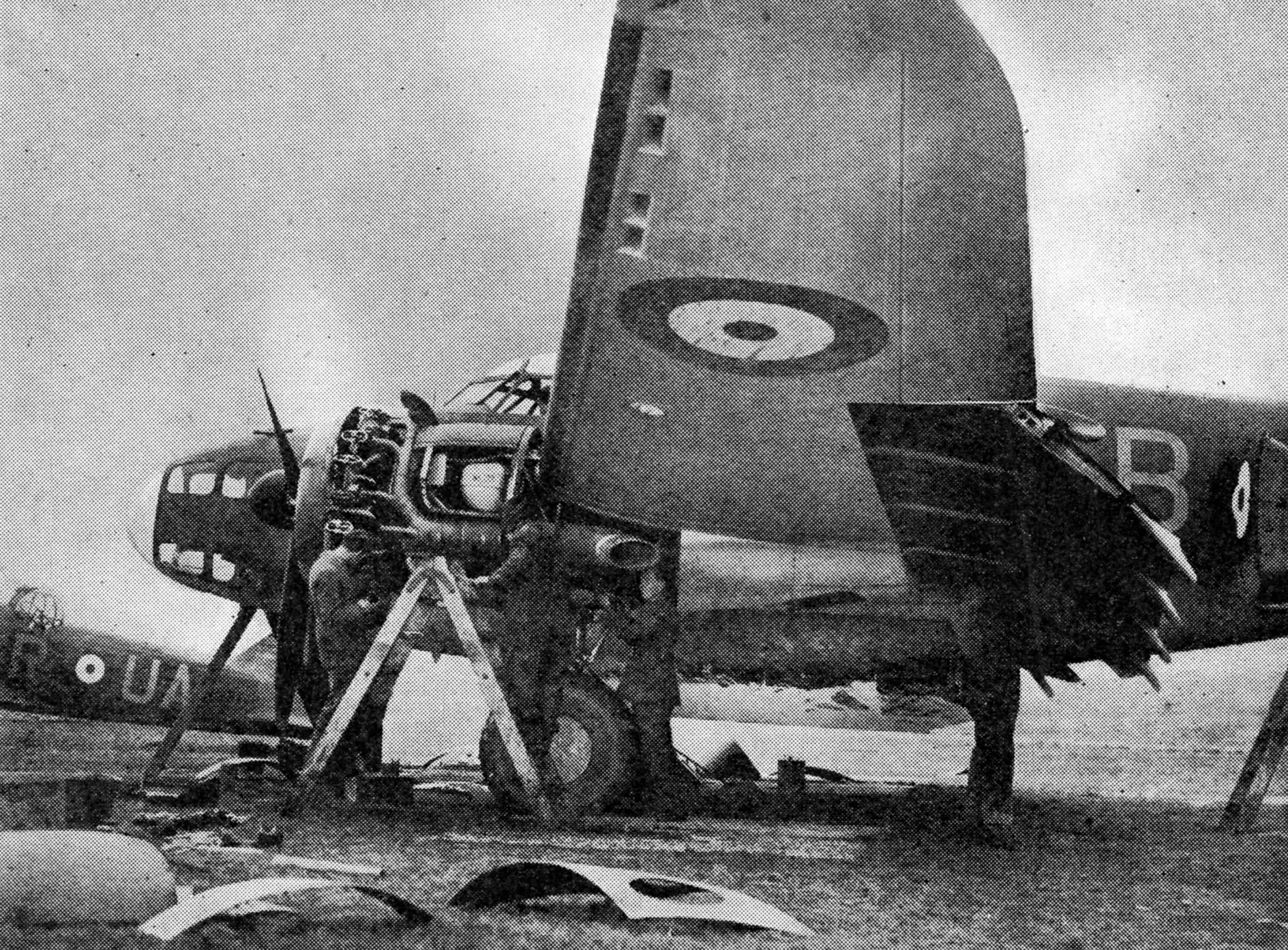
AT
WORK ON A LOCKHEED VENTURA
Repairs
to high-powered aircraft engines call for a great deal of technical
skill and patience. This ground crew is servicing a Ventura
reconnaissance bomber of the Coastal Command
The
handling of explosives is a highly specialised task. In addition to the
storage and delivery of bombs, this section of the Command deals with
ammunition, pyrotechnics for signalling, oxygen and petrol. The main
stores in which the explosives are kept are sometimes hundreds of feet
deep in the side of hills.
The salvage of crashed aircraft also
comes under the control of the Command, though only about ten per cent.
of the actual repairs are done by the Command’s own men. The depots
where they work are, however, wonderful training grounds for
aircraftsmen and, as soon as mechanics reach a high standard of skill,
they are sent to stations to work on the maintenance of aircraft in
operational use. The large repair depots and salvage and repair units
are so organized that a minor crash or damage from anti-aircraft fire
can be put right in record time. A Wellington bomber seen on a station
in the early evening ready to take off on a night operational flight in
a brand new coat of paint may not necessarily be new and straight from
the store into which it was put when delivered by the aircraft factory.
Actually it was probably over Bremen or some other German city the
night before and came back with a large hole in the fuselage where it
had been hit by “flak.” It was a pitiful sight when it came back, but
the repair gang, men and women, got to work on it and finished in time
to spray it with a new coat of paint and have it ready for another raid.
FERRY COMMAND
Obviously
the thing that the operational pilot needs most is a complete aircraft.
It is also the one form of munition of war which can deliver itself so
to speak, over great distances without the use of shipping space or
lorries or rail wagons. It can be flown and carry freight or passengers
in the process as well.
When war began, Britain was short of
operational pilots. She needed everyone she could lay hands on and had
none to spare for the routine jobs of delivering aircraft by air from
factory to the Maintenance Command depots and from there in due course
to the operational squadrons to replace those shot down or damaged in
combat. To cope with this problem, the A.T.A. (Air Transport Auxiliary)
was formed of civil pilots either too old or unsuitable for some other
reason to take part in the fierce stress of the war. Famous people such
as Amy Johnson and Jim Mollison joined. They did and still do a highly
valuable job. Their organization grew. It showed what could be done by
the air delivery of aircraft and suddenly, because of their work, the
germ of an idea that was eventually to be one of the greatest triumphs
of organization the war was to see, took shape. The idea of the air
delivery of aircraft across the Atlantic to Britain, to every theatre
of war in every part of the world, had birth. Ferry Command came into
existence.
FIRST TRANSATLANTIC DELIVERY
The
war was only a few months old when the first steps for a regular
Canada-Britain air mail service which would eventually become the basis
of a bomber ferry service were taken. A group of experienced pilots,
all men well-known on the world’s air routes, were sent to Canada and
reinforced there with civilian pilots from Canada and the United States
and service pilots from Coastal Command. A transatlantic ferry pilots’
school was opened in November, 1940, and on Armistice Day that year the
first trans-atlantic delivery of American built bombers to Britain took
place. Seven Lockheed Hudsons took off from Newfoundland under Captain
D. C. T. Bennett, D.S.O., and ten hours later landed in Britain. Their
flight went so smoothly that instructions were sent for the remainder of
a consignment of fifty to take off.
ATLANTIC
FERRY CONTROL
At
the eastern terminal of Ferry Command somewhere in Britain the control
room staff plot the movements of every new plane in its
2,000-mile
flight across the Atlantic from Newfoundland
In March,
1941, the following year, the bomber ferry came under the control of
the Ministry of Aircraft Production but remained so for only a few
months. In June, 1941, Mr. Roosevelt made it known to Mr. Churchill
that the United States government was prepared to let U.S. army pilots
and crews ferry bombers to Canada and Newfoundland and permit U.S.
civilian pilots to fly them across the Atlantic. Later the Air Ministry
again took over the ferry service and Ferry Command—now called
Transport Command—was formed. Today the Command delivers a
steady
stream of aircraft across the Atlantic by three main routes,
from
Newfoundland, from Bermuda and from Brazil to the West Coast of Africa,
the route for the Middle East.
The present headquarters of the
Command are at the Dorval airport, Montreal, described by Air Chief
Marshal Sir Frederick W. Bowhill, G.B.E., K.C.B., head of the Command
as “this splendid airport—one of the best I have known, with
uninterrupted approaches, modern layout and extensive approaches.” It
was completed sufficiently for partial use within five months of work on
it beginning. The forward base at Newfoundland from which the aircraft
take off for Britain is another feat of engineering construction. Built
on the site of an old forest camp alongside a railway, it is
inaccessible by road but it has the widest aeroplane runways in the
world. It is under snow for more than six months every year, but giant
rotary blowers keep it constantly clear by spraying the snow into banks
which sometimes are twenty feet high. Bermuda, which also had to have a
good deal of construction work carried out, is used for the dispatch of
flying boats. The Command also delivers aircraft across the Pacific to
Australia, and sends to India and the terminal airport which is now the
lifeline to China.
Regular Transport Command crews are mostly
civilians from all over the world. But the greater number of pilots who
bring new aircraft across are products of schools of the great
Commonwealth Air Training Plan. When they pass out a special course is
set them by Transport Command.
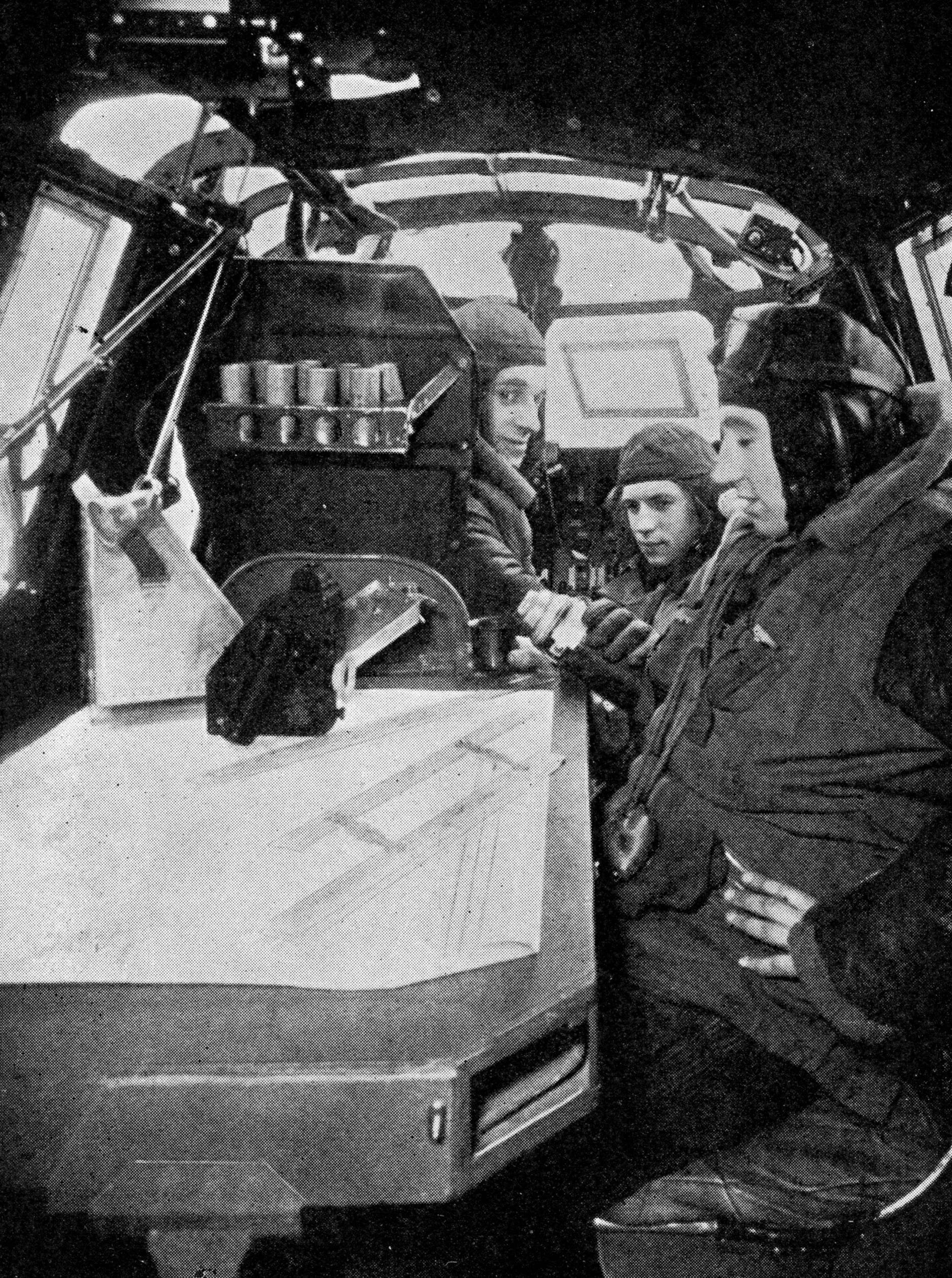
NAVIGATOR
OF A WHITLEY BOMBER
In
the forward compartment of a Whitley long range bomber, the navigator
sits at the chart table on which can be seen a bubble sextant and
parallel rulers which he uses to plot his course. At the controls sits
the captain, whilst the second pilot pours out a welcome cup of hot
coffee from a thermos flask. Faster types of planes are now operating
with the Whitleys
CHAPTER
11
Celestial
and Wireless Navigation
Map
reading. Dead reckoning. The magnetic compass. Air-speed indicator.
Ground speed. Astronomical navigation. The position line. Use of
sextant. Watches and chronometers. Reduction of the observation.
Plainsphere, air almanac and air navigation tables. Wireless direction
finding. The beam system. Meteorology. Training of navigator
NO
truer remark was ever made about the art of air navigation than that
made by the American authority, Commander Weems, when he said: “There
are four possible means of fixing an aircraft’s position,” and then
added “But there are times when all four are not enough.”
The
methods referred to by the commander were, map reading, dead reckoning,
astronomical, celestial and wireless direction finding. Each method is
best suited to certain types of problems and when Commander Weems
claimed that there were times when all four were not enough he meant
that there were circumstances in which each method would fail.
Fortunately, all four methods do not usually fail simultaneously, but
the moral is clear. The good navigator cannot afford to neglect any one
of them.
SCALE OF MAPS
The
maps in use in the R.A.F. are of three scales, each scale being a
multiple of the others. First of all there is the 1/1,000,000 map which
gives a scale of approximately sixteen miles to the inch on the map
(Fig. 1). With this scale little detail can be shown of course, but
nevertheless a large area can be put on a single map sheet. This map
then is used mostly for plotting the track and studying the general lay
of the route.
When greater detail is required the 1/500,000 map
is used (Fig. 2). This gives approximately eight miles to the
inch, and allows each feature to be depicted in greater detail. On this
map it is usually possible to recognize the towns and villages of the
countryside. Only when one comes to a very congested
neighbourhood
such as greater London or the industrial parts of the midlands or the
Ruhr valley is it essential to have still greater detail. For these
areas therefore a map of scale 1/250,000 or approximately four miles to
the inch (Fig. 3) is used.
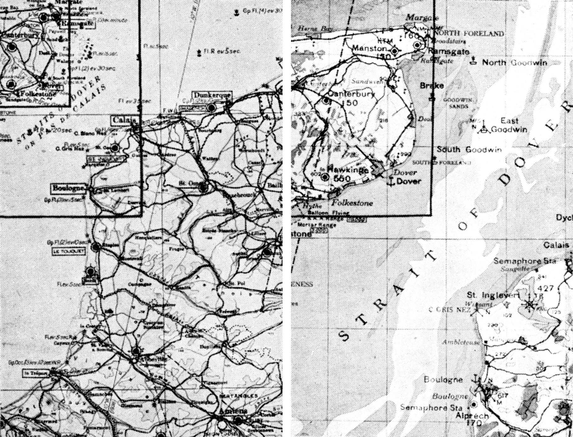
NAVIGATIONAL
MAPS
Maps used in the R.A.F. are of
three scales, each being a multiple of the others. Fig. 1 (left) is 1/1,000,000 giving
approximately sixteen miles to the inch. Fig. 2 (right) is 1/ 500,000 and gives
eight miles to the inch. In Fig. 3 (below) the scale is 1/250,000 and
gives four miles to the inch.
USE OF WIRELESS
In
general, as the flight proceeds the navigator will use maps of larger
and larger scale, and the bomb aimer will finally pick out the target
from a special large scale target map or a photograph.
Map
reading is one of the most difficult subjects to teach, or, to be more
exact, it is probably impossible to teach. It comes with experience in
the air and hours of observation. Navigation proper is a much more
exact science and comparatively easily taught to any one with average
ability. There are navigators who will bring their aircraft to within a
few miles of their home stations by navigation proper, and then take
out a large scale map of their home countryside and proceed to lose
themselves entirely.
Dead
reckoning navigation is the art of estimating the aircraft’s position
by knowledge of the direction and speed in which it has been moving.
This sounds simple enough, but in reality can be quite a complicated
process, for here, errors are accumulative. If there is an error in the
aircraft’s course or if the speed is not quite accurately known then
the estimate of the aircraft’s position will differ from the real
position and the disparity will increase with the passage of time.
There
are many sources of error in dead reckoning navigation. In the first
place, the course is set by a magnetic compass (Fig. 4), but there is
much magnetic material in the aircraft, and it is necessary to “swing”
or adjust the compass very carefully on the ground before it can be
made to give the correct reading (Fig. 5). Even after this, it is not
absolutely certain that the course as set in the air is always quite
accurate. Bombs are of magnetic material. The machine may have been
“swung” on the ground with bombs on, but what when the bombs have been
released? The machine was “swung” on the ground with its undercarriage
down, but in the air the heavy steel tubes of landing gear will fit
inside the wings.
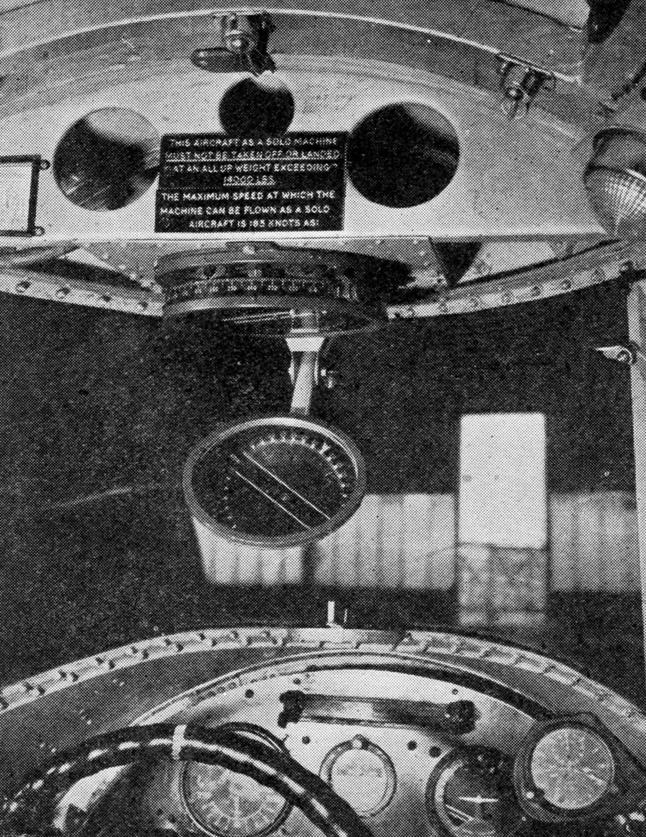
THE
MAGNETIC COMPASS
Fig. 4.
Inverted type aircraft compass. It is fixed in the roof of the aircraft
above and in front of the pilot who takes his bearings by means of a
mirror. Saving of space is effected
ADJUSTING
A SPITFIRE’S COMPASS
Fig. 5.
Magnetic compasses are very sensitive instruments, and as there is much
magnetic material in an aircraft, they are liable to be affected and
give inaccurate readings. In order to overcome this, aircraft are swung
on the ground with full load and the compass adjusted accordingly. The
Spitfire above is being swung on a specially constructed turntable
It has been known for the magnetism of an
aircraft to have been substantially changed by flying through an
electrical storm with the result the compass had considerable errors.
All these are points which have to be continually watched and checked.
In the long run, however, the magnetic compass is a superbly reliable
and surprisingly accurate instrument.
NAVIGATOR’S
CHART BOARD
Close-up
view of chart board with adjustable ruler which can be set to take into
account such factors as ground speed, wind speed, air speed and so on,
interdependent factors to be reckoned with
The next
“key” instrument required in dead reckoning navigation is the air-speed
indicator. Here again, however, any one who supposes that an air-speed
indicator always gives a direct indication of the true air speed would
be taking a very optimistic view. First of all, the instrument itself
is periodically calibrated on the ground against a master instrument
and its errors are noted. Next there is a correction to apply for the
position in which the instrument is mounted on the aircraft. This is
known as the position error or “P.E.” This is bad enough, but there is
worse to come! The instrument is measuring the forward speed of the
craft by the pressure of the air stream, so its reading depends on the
density of the air itself; the density depends on the temperature and
pressure. When flying low these adjustments to the air-speed indicator
reading only amount to minor compensations, but when flying
high
they become very large factors indeed. For example, let us suppose that
a bomber goes out on a raid at 20,000 feet where the air
temperature is -24 deg. centigrade, and that the navigator sees his
air-speed indicator at 165 miles per hour. His combined instrument
error and position error correction is usually kept on a card
pasted to the instrument board, or inside the cover of his log book. At
165 miles per hour indicated speed, the correction is +9, which means
that his corrected indicated speed is 174 miles per hour. Now he takes
a computer, that is a special slide rule for correcting air speed. At a
pressure height of 20,000 feet and a temperature of -24 deg. centigrade
the 174 miles per hour is corrected to a figure of 238 miles
per
hour. This at last is his true air speed.
Even
now, however, the
navigator’s troubles are far from over. He has found his true air
speed, but that is only his speed through the air. What of the wind?
i.e., the speed of the air over the ground. Perhaps he has a
50-miles-per-hour wind from behind him in which case he is
approaching the target at 288 miles per hour. Perhaps
the
wind is against him, in which case his ground speed is only 188 miles
per hour. Perhaps the wind is on the beam, however. In this particular
case he is not directly approaching the target but
is
drifting twelve degrees or so to one side or the other.
It would
be quite impossible in this chapter to explain all that is involved in
the term “dead reckoning” navigation, but enough has been said
to
show that it is full of pitfalls for the unwary. The point to remember
is that these pitfalls are apt to increase with the passage of time.
For example: if a navigator over-estimates his ground speed by ten
miles per hour he will plot a position ten miles ahead of his real
position for every hour that he flies. After ten hours he would be 100
miles in error. Thus it is very important
to obtain
other checks on the positions. This may be done either by wireless
bearings or position lines from celestial bodies.
Astronomical
navigation is the fixing of a craft’s position by observation of the
sun, the moon, the planets or the stars. There are many varieties of
method, but the underlying principles are similar. In general too,
there are three features common to every method. First, the process of
“taking a sight,” that is, measuring the “observed altitude” or angle
of elevation of the celestial body. This is done with a sextant.
Secondly it is necessary to obtain the exact time of the observation by
a chronometer or an accurate watch. Thirdly there is the process of
reducing the observations of sextant and watch to position lines on the
chart. This process, however, involves some small amount of calculation
and the use of a naval almanac and some mathematical tables.
It
is not possible to obtain the exact position from the observation of
any one body. It is only possible to obtain a “position line.” That is,
a line somewhere upon the length of which the observer is situated. The
position line is at right angles to the direction in which the body is
seen. In order to fix the position completely it is necessary to make
observations of two celestial bodies and where the position lines of
the two cross is of course the exact position (Fig. 6).
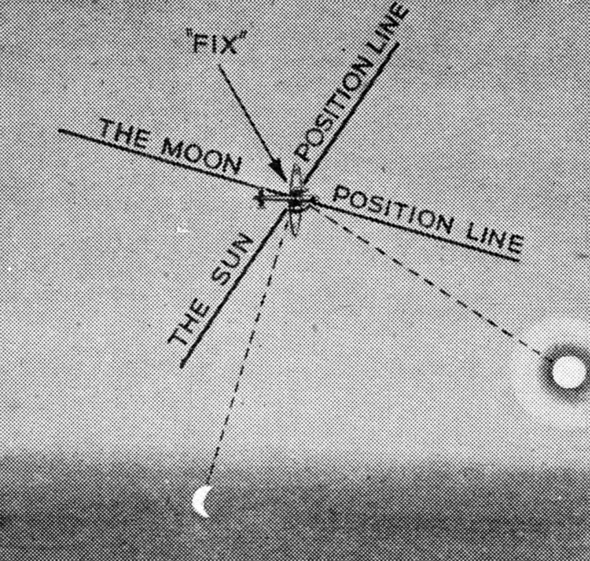
FIXING
THE POSITION
Fig. 6.
Diagram illustrating how bearings are taken by observations from two
celestial bodies. The position lines are at right angles to the
direction in which the bodies are seen, the point at which they
intersect is the “fix”
Air
navigation has its roots in sea navigation. The principles are the same
and many of the processes are exactly analogous. The marine navigator
would however find difficulty in recognizing much of the air practice.
The lesser degree of observational accuracy in the air coupled with the
urgency of extreme speed has resulted in the development of
methods far quicker and simpler than were ever dreamed of by navigators
at sea.
Despite this it is interesting to find that a marine
sextant differing little in essential design from those which have been
used at sea for generations is still used very successfully in some
circumstances in the air. The flying-boat does most of its flying low
over the water on convoy work and anti-submarine patrol. The air over
the Atlantic is both cloudy and windy, but when the pilot sees a patch
of sunlight shining on the sea ahead of him he may dive down and fly
even lower above the surface—no higher than the bridge of a ship. His
navigator may then get a “snap” sight of the sun’s altitude above the
sea horizon. The resulting position line may be exceedingly valuable to
the navigator who may have been working on nothing but “dead reckoning”
for the past twelve hours. The particular type of sextant now issued to
all our flying-boat crews for this purpose is a development of one which
was originally made for Alan Gerbault, the French yachtsman who sailed
the Firecrest
single-handed across the Atlantic Ocean.
Those
navigators however who fly high at night, where no natural horizon is
available, do not get this advantage. To them the taking of a sight is
a more laborious process, for they must use a bubble sextant in which
the natural horizon is replaced by a bubble floating in a liquid. On the
ground this instrument will measure an altitude to one minute of arc,
and would continue to do so in the air if only the aircraft could be
persuaded to fly truly straight and truly level. Unfortunately this
never happens. In practice, the aircraft, even when it appears to be
flying straight, is in reality weaving slightly from side to side. The
motion may be imperceptible to the pilot but to the bubble of the
navigator’s sextant it causes large and fluctuating errors. This sextant
is one of the many devices on which an air crew’s safety depends.
The
only course open to the navigator then is to take many sights and
average them. The taking of an observation with a bubble sextant (Fig.
7) may be a far more laborious process than the single observation from
the bridge of a ship at sea. It often entails standing at an open hatch
with frozen fingers for five or ten minutes at a time patiently recording
a series of from six to two dozen individual observations. In addition
to cold and fatigue, lack of oxygen often renders accurate work even
more difficult (Fig. 8).
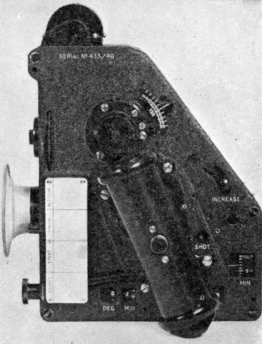
MARK
IX AVERAGING SEXTANT
Fig. 7.
Bubble sextant used for taking bearings on celestial bodies. It
incorporates a device for averaging the results of six observations.
The bubble replaces the horizon
TAKING
AN OBSERVATION
Fig. 8.
Navigator of a Sunderland flying-boat taking an observation by means of
a Mk VIII bubble sextant. Depending upon the degree of accuracy, he may
have to average out the results of as many as two dozen observations
because of the unsteady movement of the aircraft
The first bubble sextants issued were
designed at the Royal Aircraft Establishment at Farnborough long before
the days of R.A.F. expansion, and at a time when very few navigators
were trained in the use of the sextant. The demand for the instrument
was slight and the sextant was in no way designed for mass production.
It was a good rugged instrument and sundry improvements ran up to a MK
VIII. In about 1938 it was realized that with the enormously increased
range of modern aircraft celestial navigation was going to be more in
demand, and with the coming expansion in view the specification for a MK
IX sextant was drawn up so as to be capable of mass production. This
sextant incorporated an ingenious mechanism for averaging the result of
six observations, and it could be produced in the large quantities
which were required. Although there are a number of MK VIII sextants
still doing good service, the MK IX averaging sextant is now standard
in the R.A.F.
Without accurate knowledge of Greenwich Time the
navigator would be unable to work by astronomical observations, and it
is to the Admiralty that we owe the development of the
chronometer, and indeed accurate time-pieces of all kinds. The real
chronometer is a wonderfully accurate and very delicate piece of work.
Not only does it keep time more accurately than is really necessary for
air navigation, but the treatment it receives, the fluctuations of
temperature and the vibration are sheer cruelty to such a delicate and
expensive instrument.
LONG PATROLS
In
practice the endurance of aircraft is not great, and time signals are
plentiful. Flying-boats are normally on patrol for twelve or fourteen
hours while bombers do not as a rule fly for more than eight or ten. The
watches issued to navigators in the R.A.F. are wrist watches of good
quality which will keep time accurately enough over flights of such
duration. They are fitted with a rotatable bezel engraved with a scale
of seconds, so that if the long centre seconds hand is not set
absolutely accurately, it may be made to read correctly against this
outer scale.
When the sextant observation has been made and the
exact time of the observation has been noted, it remains to reduce the
observation to a position line on the chart. This sounds a very
formidable process and until a few years ago it was so. Now, however,
it has been made very easy, for those responsible for developing the
methods of celestial navigation to be used in the R.A.F. have realized
that only the most simple processes were practicable and workable in
the air. So simple has it been made that it has been found possible to
give navigators as little as three weeks’ instruction in celestial
navigation, for them to be able to navigate successfully.
This
simplicity has been achieved by the production of three things: a
“planisphere,” the “air almanac,” and the “air navigation tables.”
Little or no arithmetic is required, and it is not even essential to
know the principal stars by name. The planisphere is a kind of map on
which the positions of the stars can be found. The principal stars used
in navigation are numbered, the numbers correspond with those in the
air almanac and also with those in the air navigation tables. The
numbers in the air navigation tables are “thumb-holed,” so that a pupil
may make an observation and turn up the right page in the tables
without even knowing the name of the star with which he is working. In
practice, of course, the pupil soon becomes interested and learns to
recognize and name the dozen or more stars which he requires. In the
old days it used to require some twenty minutes’ work with logarithms
before use could be made of an observation: now the position line is on
the chart in two or three minutes.
The limitations to the use of
celestial navigation are firstly due to the fact that there is only one
sun by day, whichwill give a position line but not a “fix.”
Secondly, of course, it is altogether useless when the sky is obscured
by cloud.
USE OF WIRELESS
As
with other aids to navigation there are many variations in the use of
wireless. Essentially the process consists of receiving a signal and
detecting the direction from which it is coming. This direction can
then be plotted as a bearing on the map and the transmitter which sent
the signal will lie somewhere on that line. If a second bearing can be
obtained cutting the first one, the point where they cross will be the
actual position or “fix” as it is called (Fig. 9).
GETTING
A WIRELESS “FIX”
Fig. 9.
A signal from the aircraft is picked up by two or more D.F. stations
who note the bearings. These are then plotted, and where they intersect
shows the position.
Now there are
two ways of using this; the directive reception may be on the ground or
it may be in the aircraft. First, let us consider the organization on
the ground.
Suitably disposed all over the British Isles are
many direction finding stations. They are arranged in a number of
different groups. There are usually three stations working on the same
wave length in each group. If an aircraft is lost or uncertain of its
position it calls up on the appropriate wave length and asks for a
“fix.” Each of the three “D.F.” stations receives the aircraft’s signals
and notes the bearing, that is the direction from which they are
coming. Now one of the three stations is a master station and the two
others send in the bearings they have received to this one. In the
master station all three bearings are plotted and their intersection is
the position of the aircraft.
LIMITS TO NAVIGATION METHODS
The
master station then signals to the aircraft telling it where it is.
This sounds rather a roundabout process, but in practice the service
can be extraordinarily prompt. An aircraft is often given
its “fix”
within one minute of asking for it. In some circumstances a navigator
may ask for a single bearing rather than a position, which saves a
little time.
There are, of course, various drawbacks and
limitations as there are to all methods of navigation. In the first
place, if the aircraft is close to enemy units and not already
discovered by them, it is undesirable for it to break wireless
silence and so disclose its position equally to the enemy. Secondly
there is the possibility of an enemy ground station answering the
aircraft’s call and giving it a bogus position. This happened to the
navigator of a night bomber in the first few months of the war. He was
returning across the North Sea having been badly damaged. The machine
was low over the water and only just holding its height. The navigator
wanted a bearing to help him steer for the nearest point on the English
coast. No sooner had his wireless operator made the signal than a very
loud station replied giving him a perfectly false bearing. Fortunately
the bearing given was so wrong as to be quite absurd. It was ignored
and the aircraft got safely home. To guard against incidents such as
this the wireless signals are now put into code and there is a
recognition procedure to ensure that both ground station and
aircraft can be certain of each other’s identity. A third limitation of
this type of wireless aid is that when there are perhaps a hundred or
more bombers in the air, the ground stations get so much overworked
that the system is bound to become very much congested.
The
other way in which wireless bearings are used is by putting the
directive receiver into the aircraft. Here the wireless set has a loop
receiving aerial, and the wireless operator in the aircraft measures
the direction from which a signal is coming. Here the problem is to find
suitable transmitting stations upon which to take bearings. The German
broadcast transmitters usually close down during our raids to
deny
us this assistance. The Germans themselves established a number of
beacon transmitters specially for the purpose and moved them about and
changed their call signs and wave lengths hoping that we could not use
them as well. The broadcasts of the B.B.C. transmitters, of course,
have been arranged in such a way that it is impossible for an enemy
aircraft to get an accurate bearing from them at any time.
BEAM SIGNALS
There
is one other variety of wireless aid to navigation. That is the beam
system which is so universally used on the airlines all over the United
States, and which has been brought to a very advanced state of
technical development by the Germans. Here a ground station emanates a
beam signal in a certain direction. The crew of the aircraft can tell
whether or not they are in the beam and so can travel along it. This
has the disadvantage, however, that it can only be used on one fixed
route and in consequence does not help the navigator who wants to
travel in another direction.
NAVIGATOR
PLOTS HIS COURSE
Navigator’s
station in a Short Sunderland long range flying-boat. The captain is
instructing his crew to stand by ready for the take off. The navigator
is already at work plotting his course. Sunderlands fly mostly far out
over the sea, so a very high standard of navigation is required
comparable, in fact, with that of a transatlantic liner, but with far
more variable conditions
It would be impossible to
give the reader a proper conception of navigation in the R.A.F. without
mention of the Meteorological Service. Every R.A.F. station has its
“Met. Office,” where the forecasting officer and his assistants study
the weather maps and prepare their forecasts. The navigator’s training
includes a short course of meteorology, and although he is not expected
to be an expert on the subject he should know enough of the
meteorologist’s work to enable him to get the full value of his advice.
This training also gives him some sympathy for the weather man who is
attempting the, at times, impossible task of forecasting the weather
round these islands. It is to the “Met. Office” then that the navigator
goes last thing before he flies. Here he studies what is known of the
weather over his route, and he is told what to expect of the
wind,
the cloud amounts and the visibility. Often the forecast is correct,
usually it is a pretty fair indication of what to expect, sometimes it
is quite wrong: no fault of anybody, the weather has just “pulled a
fast one” again.

NAVIGATION
EXERCISES FOR OBSERVERS
Before
they become fully operational, navigators are given a final test to make
sure that they are fully competent to discharge their very responsible
job. The navigator (above, left) seated behind a board on the other
side of which is the instructor, is acting in accordance with orders
given to him. Electrical instruments record the accuracy with which he
carries them out
NAVIGATOR’S SKILL
Each
method of navigation works to its best advantage in some conditions,
but has drawbacks or limitations in others. No method is perfect, and
there are circumstances in which each may be extremely inaccurate. A
navigator is rather like a foreman with various workmen at his command,
for he must know which of them will serve him best for any particular
part of the job in hand. Often too they will come to him with
contradictory pieces of evidence and he must weigh up in his mind
which, in the circumstances, is more likely to be correct.
The
good navigator must first of all study the theory of his subject in the
class room. Next he must accumulate a store of experience in the air to
learn just how the theory works out in practice. Then as each
perplexing problem presents itself he must use both his knowledge and
experience to make what really amounts to an intelligent guess.
In
this chapter we have seen what a very important role must be played by
the navigator of any aircraft. There have been quite a number of
occasions during the Second World War when flying operations against the
enemy have had to be carried out under really unsatisfactory weather
conditions, and when almost everything has depended on the skill and
alert brain of the bomber’s navigator.
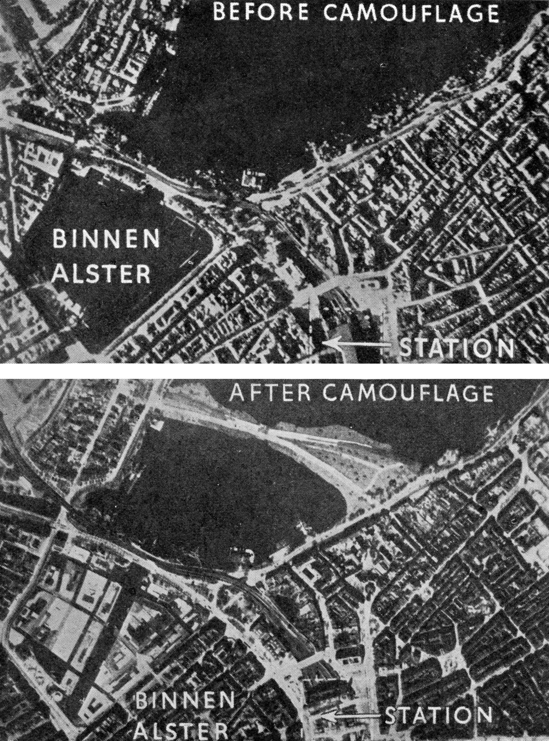
CAMOUFLAGE
REVEALED BY THE CAMERA
The
value of aerial photography is well illustrated by the above
photographs which show how the Binnen Alster, the innermost of two
lakes in the centre of Hamburg, was camouflaged with rafts to look like
a built-up area. A dummy of the Lombardsbruecke, a vital road
and
rail connexion, was reconstructed, as shown, about 600 yards north of
its original position. Photographic interpretation experts soon
discovered the ruse, very ingeniousthough it was
CHAPTER
12
Air
Photography in War
Purposes
of air photography. Interpretation staff. Stereoscopic photographs.
Vertical and oblique photographs. Focal length of lenses. Measurement
of distances. Mosaics. Night photography. Use of the camera gun.
Training of photographic personnel
IN describing the work
of the R.A.F., detailed attention must be given to the activities of
its air photographers, the more so as their work has a great bearing on
the efficient performance of many urgent national duties.
The
limitations of visual reconnaissance, due to speeds and heights at
which aircraft travel and to the lengthy training necessary before
observers can be relied upon to discern and identify the important and
to disregard the unimportant, make it expedient that trained staff
officers, able to study air photographs methodically, and at comparative
leisure, and in conjunction with all the other information available,
should be the men to draw the vital conclusions as to enemy’s
dispositions and intensions.
MODERN DEVELOPMENTS
Air
photography for military use was already of great assistance in the war
of 1914-1918, and in the intervening years calls have been constantly
made on the inventive genius of the scientific world, on the camera
designer, the optician, the chemist, the electrician, and such
practical technicians as the fast-working press-photographer—each to
play his part in the perfection of apparatus and processes, and to
promote speed, accuracy and economy to the greatest degree.
From
clumsy plate cameras and slow, improvised dark-room practices have been
evolved highly efficient electrically operated film cameras, with special
lenses, light filters, shutters, and so on, modern mobile dark-rooms
fitted with the latest automatic devices to ensure perfect and speedy
production of both negative and prints, and self-contained lighting,
heating and refrigerating units ensuring efficiency in any climate (Fig.
1).
The
pursuit of detailed and extensive knowledge of enemy
resources and dispositions must inspire all the important activities of
the air photographer.
INSIDE
A MOBILE DARK ROOM
Fig. 1.
The R.A.F. employs large numbers of mobile dark rooms for the rapid
processing of films in the field. These are fitted with
self-contained lighting, heating and refrigerating
units ensuring
efficiency in any climate. The compact layout of one of these vans is
illustrated above
PHOTOGRAPHIC PERSONNEL
Personnel
of the R.A.F. who are intimately connected with air photography can be
classified under three heads. First there are those whose duty it is to
navigate the aircraft over the area that is indicated, and there to
take the photographs. Second comes the technical personnel on the
ground, performing subsequent dark-room processes and producing the
finished prints, being also responsible for the maintenance of
all
apparatus. Finally there is the interpretation personnel, whose work
consists of examining each print, extracting from it the fullest
relevant information, and passing this information to the staffs and
departments concerned in an appropriate and intelligible form.
Before
going into further detail let us consider the main purposes fulfilled by
air photography, since many different demands on procedure are made.
Naturally to the three fighting Services speedy and accurate information
of enemy activities is vital. Again, the Ministries of Economic
Warfare, of Shipping, of Home Security, and so on, can gain valuable
information from air photographs, their demands in this respect being
far from infrequent.
VALUE OF AIR PHOTOGRAPHS
The
main purpose of air photography is for reconnaissance work. An army
commander today is reluctant to contemplate any operation unless he has
the most accurate and recent information possible of enemy terrain and
enemy disposition, actual and potential, relevant to the occasion.
Again, the information which is vital to naval operations regarding
numbers and types of vessels in enemy harbours, concentrations at sea,
the effective state of maintenance and repair facilities at port, and
so on, can often be obtained with accuracy and speed by means of air
photography.
To the Air Force itself early information as to the
results of bombing raids, for example, obtainable mainly by means of
air photography, is essential to the most efficient and economical
concentration of further activities.
Mapping from air
photographs is another important development, whether it be for the
study of hitherto uncharted territory over which operations are
contemplated, or for filling in additional detail on maps which already
exist.
As soon as details of a required photographic mission are
received, an aircraft crew is selected, decisions are made as to what
type of camera with what focal length of lens and with what light filter
is to be carried, how many exposures may be required, and what
procedure should be adopted. All available maps and other means of
identifying the objective are examined, and a weather report is
obtained. The intelligence ofiicer is consulted as to the probable
intensity of hostile interference and how it may best be circumvented.
While final decisions are being made, the fitting in the aircraft of the
camera and its releases and sights goes on. The testing of each piece
of apparatus as it is installed is a necessary precaution.
The
actual taking of the photographs is not less responsible a job than is
their subsequent careful processing. It may be necessary to manoeuvre
about while clouds clear, and to evade hostile aircraft, until,
photograph by photograph, pilot and crew have achieved their mission.
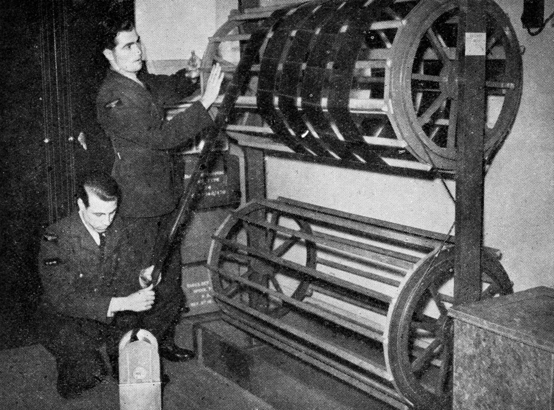
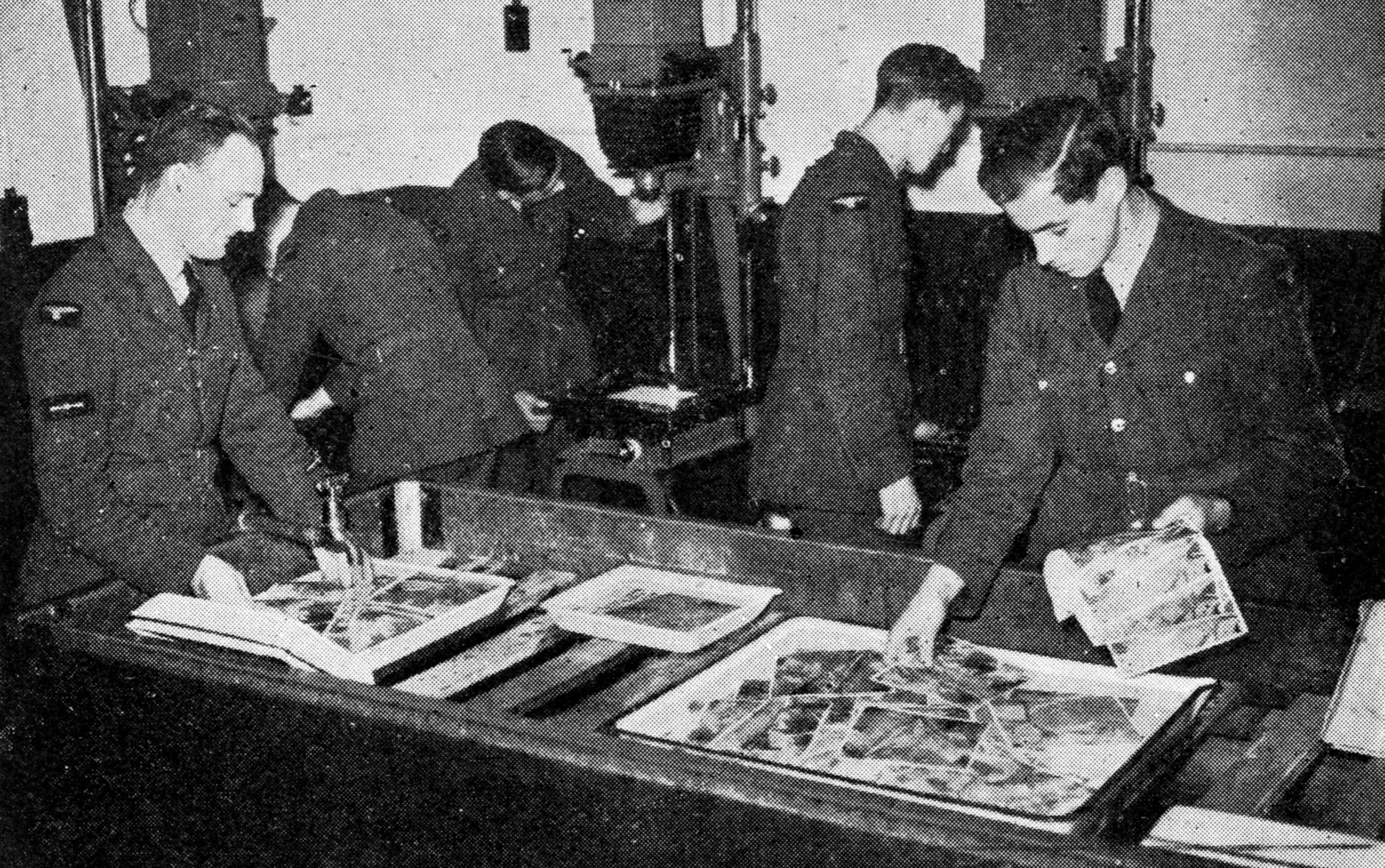
RUSHING
OFF THE FIRST PRINTS
Fig. 2.
The aircraft has returned with its precious exposures. These are
hurried off to the dark rooms where everything is ready. They are
quickly developed and dried on large drums (above) after which prints
are made (below) and sent to the interpretation staff for detailed
examination
As
soon as the aircraft lands the exposed film is handed to members of the
ground technical staff who hurry off to the dark rooms with the
precious magazines. Here all has been prepared; developing and fixing
solutions have been made up, processing tanks filled, washing and drying
appliances are ready to receive each film negative at the appropriate
stages, and printing machines waiting to rush off, as may be required,
either first proofs or large quantities of prints (Fig. 2). Both speed
and efficiency are essential, and members of the section work in teams
so that no time is lost. In the case of reconnaissance photographs, a
few prints from each negative are soon placed in the hands of members
of the “interpretation” staff who, in their turn, are holding
themselves in readiness to carry smoothly forward the sequence of their
duties (Fig. 3).

INTERPRETATION
STAFF AT WORK
Fig. 3.
The above photograph, taken from the film “Target for Tonight,” shows
the photographic branch at Bomber Command where experts are busy
examining the latest batch of photographs received from an aircraft
just back from an enemy area which is to be bombed
INTERPRETATION WORK
At
first sight the advantages of such specialized team work may not be
apparent. It is, however, no longer drummed into us that the camera
cannot lie, and even though many of the objects depicted—buildings,
railways, rivers, roads and so on—are features familiar to all, it
should be remembered that photographs suffer from the fundamental
limitation that objects of three dimensions are being recorded
on
a two-dimensional surface. We know, on looking at a photograph taken on
the ground in the plane normal to human vision, that the image of a man
standing in front of a house, for example, is not just a flat object in
the same plane as the wall of the house, nor is the house itself
without the third dimension that nowhere actually exists on the surface
of the print. Our innate knowledge and imagination, however,
automatically rouses a sub-conscious appreciation of the third
dimension, which in direct human vision is made evident by our two eyes
each seeing actual objects from a slightly different view point. The
effectiveness of this is most marked at close range. For obvious
reasons the majority of air photographs have to be taken vertically
from great heights, and objects are seen from a normally unfamiliar
point of view. Thus only the roofs of buildings may be seen, trees
appear as round objects with nothing beneath, and troughs of valleys
appear to be no further distant than the crests of hills. These
generalizations must be modified to some extent as regards sunny days
with the sun fairly low in the sky, and long shadows accentuate the
mind’s perceptions of the third dimension.
A
correct or closely approximate appreciation of this third dimension is
necessary for obtaining the fullest information about the details of an
area under review, and all the specialist skill of the photographic
“interpreter” is called into play, whether it be by means of
pairing photographs taken from slightly different viewpoints
for
stereoscopic viewing, by examining shadows, tracks, and so on, or by
other intuitive methods. This problem is dealt with later in the
chapter.
There are a thousand and one details which might well
escape the notice of the uninitiated, but which enable an
interpreter to draw definite conclusions. Nor will he allow himself to
be misled by any methods which the enemy may have adopted to deceive
the ordinary “reader,” such as camouflage, substitution of dummy objects
for real ones, and other similar devices.
In passing, reference
may be made to the necessity for correct assessment of scale, and
therefrom of distances between objects depicted on the photograph.
Minute variations of the camera axis from the vertical, due to
uncontrollable movement of the aircraft, can cause appreciable
variations of scale in different parts of the same photograph (Fig. 4).
All these must be determined for highly accurate measurements to be
made.
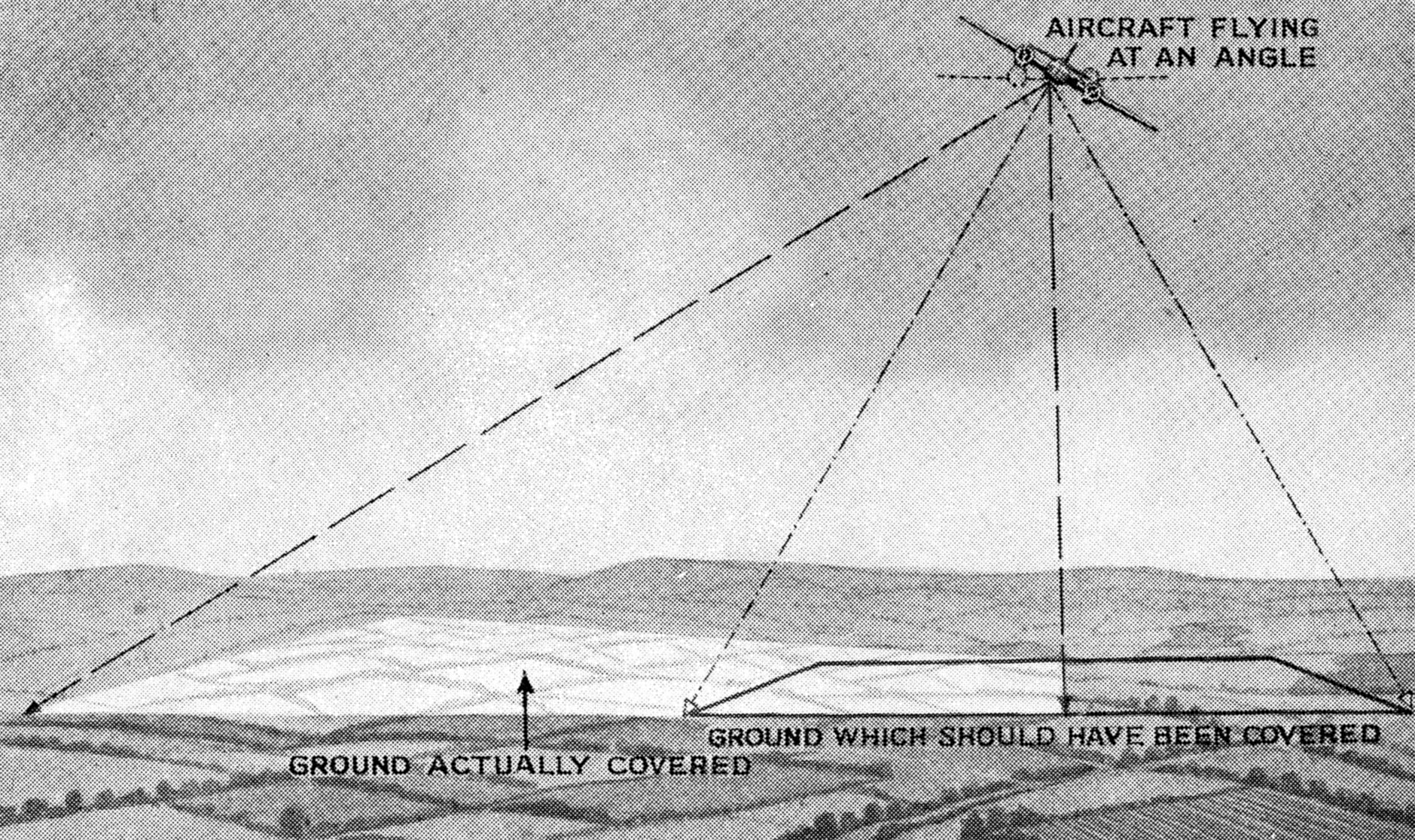
HOW
DISTORTION MAY OCCUR
Fig. 4.
Minute variations of the camera axis from the vertical, due to
uncontrollable movement of the aircraft can cause appreciable
variations of scale in different parts of the same photograph as shown
exaggerated in the diagram above. The photograph will be oblique
So, armed with the report furnished by the pilot who
undertook the mission, with maps, instruments, previous records and
other information the interpretation staff get down to work. As soon as
they are to hand, all photographs are quickly identified from maps or
previous knowledge, and a quick selection is made, discarding prints or
negatives which may be superfluous. The total number of copies required
from those selected is determined by reference to the original order
and then, quoting the serial registration numbers which are
automatically recorded on each, instructions are speedily sent to the
ground technical staff to run off the required number of prints with
the least possible delay.
Meanwhile, a more detailed examination
of the first prints of the photographic mission is taking place.
Compared as necessary with photographs of the same area previously
taken, changes in detail, due, maybe, to raids, to movements of
shipping at ports, to new military or industrial construction, and so
on, are assessed. Fig. 5 shows a photograph taken just after a raid on
Lille.
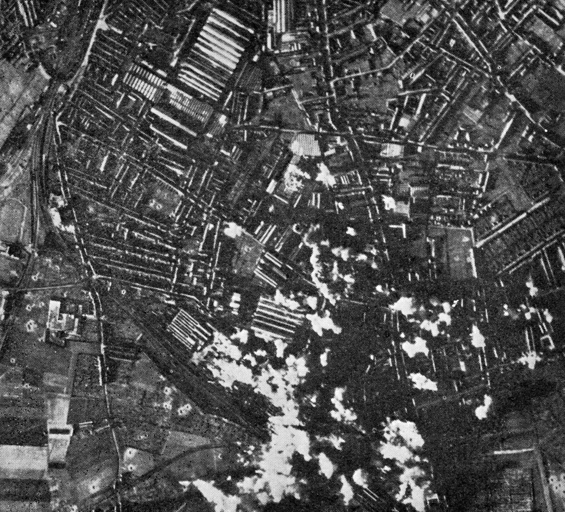
PROGRESS
OF A RAID ON LILLE
Fig. 5.
Photograph taken during a heavy daylight attack on the important steel
and engineering works at Lille and showing how rapidly the attack
developed. Smoke from fires which have been started, together with
bursting bombs, reveals that hits have been made on the eastern group
of buildings and also on other factory buildings to the south and the
north-west
As each piece of important information comes to light it
is marked by conventional signs, and, after careful checking against
other available data, noted on a memorandum. Although photographs are
generally taken with a view to studying some clearly defined operation,
the interpreters frequently light upon valuable indications of enemy
activity in hitherto unsuspected directions.
When each
photograph has been thoroughly combed for information, what has been
gleaned is noted on duplicate copies as they stream in from the
printing section, points of individual importance being emphasized to
suit each recipient. Then by quickest route, the annotated prints,
together with such explanatory notes as are necessary are distributed
to the various headquarters and departments where all the information
they reveal plays a very large part in the issue of operation orders
and other action.
HEIGHT OF OBJECTS
It
would be well to mention here how it is that the height of objects in
vertical air photography can be appreciated. It is, of course, only in
the centre of an air photograph that are recorded the absolutely
vertical light rays reflected from objects on the ground.
Three-dimensional objects which appear towards the edges of the
photograph are recorded by rays which have a minute, though appreciable
obliquity, and consequently there is recorded in the case, for instance
of a building, a minute oblique portrayal of the wall or walls
which appear as being nearest to the centre of the photograph.
TAKING
STEREOSCOPIC PHOTOGRAPHS
Fig. 6.
When a person looks at an object, the separation of his eyes, each of
which sees the object from a slightly different point of view, promotes
an unconscious appreciation of the third dimension. Thus, if two
consecutive air photographs are taken with an overlap of about
two-thirds, and viewed simultaneously, one by each eye, through a
simple optical device, a similar appreciation is obtained
stereoscopically. The diagram illustrates how these photographs are
taken. The separation between the photographs must be calculated with
great accuracy or the earth’s contours will appear to be either
over-exaggerated or inadequate
In
the case of normal human vision of actual objects the separation of the
eyes, each, therefore, seeing from a slightly different point of view,
promotes an unconscious appreciation of the third, less obvious
dimension. Thus it is found that if two consecutive air photographs are
taken with perhaps a slightly exaggerated separation (Fig. 6) rather
more than proportionate to the height of the aircraft, a similar
appreciation is obtainable stereoscopically, a simple optical
arrangement (Fig. 7) enabling the two photographs to be viewed
simultaneously, one only by one eye and the other by the other. This
method is equivalent to looking at the earth through the two eyes of a
giant. The appropriate separation is roughly that needed to give a
two-thirds overlap. Too great a separation gives too exaggerated an
effect to heights, and too small a one a quite inadequate indication.
Limitations imposed when applying this principle to oblique photographs
are obviously so great that very little advantage has ever been taken
of it.
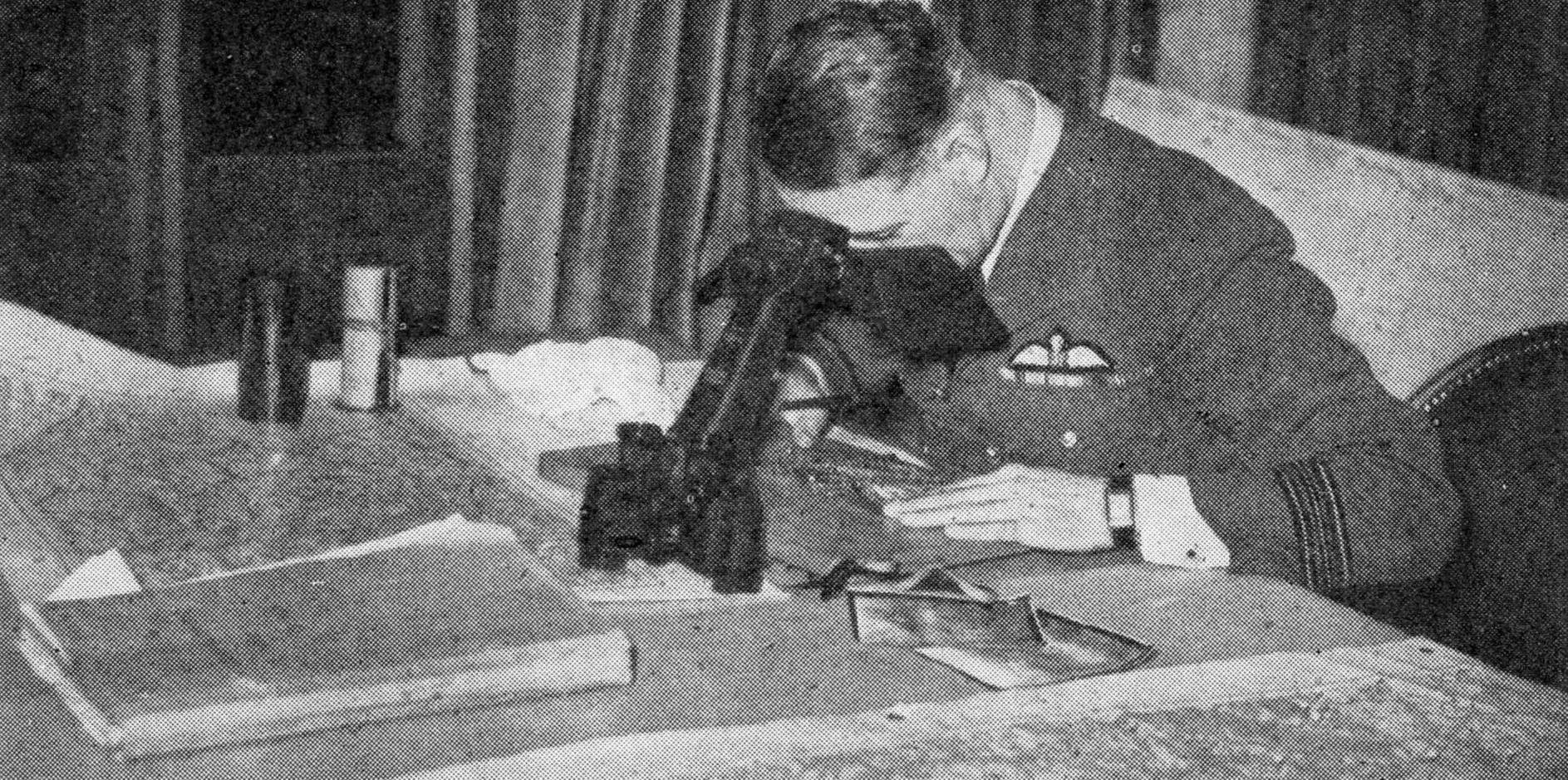
STEREOSCOPIC VIEWING
DEVICE
Fig. 7.
When stereoscopic pairs of photographs are taken they are viewed
simultaneously through a simple optical device, like that shown above,
by means of which an appreciation of the third dimension can be
obtained, objects photographed appearing to stand out in relief
By far the larger number of air photographs taken by the
R.A.F. are vertical photographs, that is, taken with the lens of the
camera pointed directly downwards and providing valuable and
informative views of the ground in plan (Fig. 8.)
Nevertheless,
there are occasions when photographs giving an immediate appreciation
of the heights of ground features are of extreme importance. Such
photographs, which in appearance are similar to those taken from the
tops of high hills, can be obtained if the camera is mounted in a low
flying aircraft so that its axis is slightly depressed from the
horizontal. The photographs are “obliques” (Fig. 9).
OBLIQUE
AND VERTICAL PHOTOGRAPHS COMPARED
Fig. 8 (lower). Vertical photograph of
the docks at Dunkirk taken with the camera lens pointing vertically
downwards. Fig.
9
(above). Oblique photograph of the same area taken with the lens
pointing slightly below the horizontal. Vertical photographs can be
taken from any height, but obliques, to be of any value, must be taken
by low flying aircraft. The letters indicate warehouses and dockside
buildings before and after destruction by air attacks
The
comparative advantages and limitations of each type are borne in mind
by the authorities when detailing photographic missions.
The
vertical photograph has the advantage that it can be usefully taken
from any height, however great, thus reducing the chances of any
hostile interference.
By fitting lenses of longer or shorter
“focal length”—the distance, that is, between the focal point of the
lens near its centre, and the centre of the negative behind it—the
“scale” of the photograph—expressed as a simplification of so many miles
on the ground to so many inches on the photograph, or as a
representative fraction—can easily be decreased or increased as may be
desired for any given height, the area of ground covered on plates of
exactly the same size being, of course, at the same time,
proportionately decreased or increased.

FOCAL
LENGTHS OF LENSES
Fig. 10.
Diagram showing areas of country covered by three lenses of 14-inch,
5-inch and 20-inch focal length pointing vertically downwards from a
height of 20,000 feet
As an example, if an
aircraft flying at 20,000 feet uses a camera of standard film dimension 7
in. by 7 in. fitted with a lens of 14 in. focal length, the scale of the
resultant photograph expressed as a representative fraction will be
1/17143. In other words 1 inch on the photograph represents 17,143
inches (or roughly 1,430 feet) on the ground, and the area of ground
covered by the whole negative is seven times 1,430 feet square, or
10,000 feet by 10,000 feet. By substituting a lens of 20
inches
focal length, the scale is increased to 1/12000 but the area
covered reduced to 7,000 feet by 7,000 feet. If a lens of only 5 inches
focal length is used, the scale is reduced to 1/48000 but the area
covered increased to 28,000 feet square or just over twenty-eight
square miles. These points will be readily understood from a study of
Fig. 10.
Obviously the smaller the scale of photographs taken
from the air the more difficult it is to distinguish and identify small
objects on the ground, and the solution is not to be found in
enlargement from the negative because the grain in its emulsion, also
proportionately enlarged, may itself be in the region of as much as
1/200th of an inch.
If, therefore, a wealth of accurate detail
is needed, as for instance in assessing bombing results on specific
objectives or in identifying small craft in harbours, it is necessary
to use a lens of long focal length, and make a correspondingly greater
number of successive exposures, to cover a given area of country. On
the other hand, for such a purpose as the preliminary examination of
large tracts of country in which the enemy is suspected of establishing
new aerodromes, for example, it is easier and more economical to use a
lens of short focal length. Oblique photographs by way of comparison,
can normally only be taken from low altitudes—say, for instance, from
1,500 to 3,000 feet—with a lens of medium focal length, and in a camera
which is aimed at an angle of fifteen to thirty degrees below the
horizontal (Fig. 11).
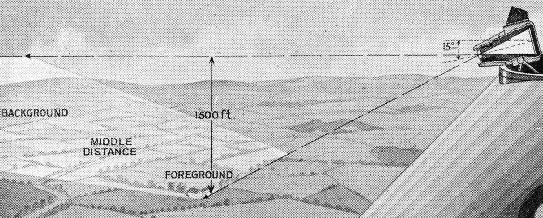
THEORY
OF OBLIQUE PHOTOGRAPHY
Fig. 11.
Diagram showing areas of country covered by an oblique hand camera with
the lens pointing fifteen degrees below the horizontal. Low flying
aircraft are usually employed
USING
A HAND CAMERA FOR OBLIQUE SHOTS
The
observer-gunner of an army aircraft on reconnaissance is seen above
taking oblique photographs with a hand camera. For such shots the
camera lens is pointed between fifteen and thirty degrees below the
horizontal. A lens of medium focal length is generally used
Difficulties such as those involved in
efficient mounting preclude the adoption of lenses of long focal length
and higher flying. Oblique photography, therefore, is usually confined to
special objectives, or territory where the likelihood of serious
hostile interference is remote. A typical instance of where obliques
may well be of more use than verticals, suggests itself in fast moving
desert warfare, where photographs from several angles of forts, and of
strong points on escarpments or in defiles can be of immense value in
determining what tactics should be adopted and even what special
equipment is necessary for an attack. Such a photograph is shown in
Fig. 12.
DESERT
WARFARE SEEN FROM THE AIR
Fig. 12.
Oblique photograph taken from an R.A.F. aircraft during the British
advance on Bardia, Libya, in January, 1941. Advancing detachments of
the Royal Armoured Corps are seen about to capture an Italian defence
ring, which is seen in the centre of the picture
Easily understandable, these photographs can be
supplied without delay, even by message dropping to the army units
engaged in the actual operations, the information given being
immediately utilized to best and utmost advantage.
The
measurement of distances between objects is far easier in a vertical
than in an oblique photograph. In the case of the former unless there
was any abnormal deviation of the camera axis from the
vertical,
the scale can usually be regarded as constant all over the photograph,
whereas in the latter the scale progressively decreases from the
foreground at the bottom of the print until the horizon near the top is
reached, a fan shaped area of country being restricted to a rectangular
photograph. If, with an oblique, the angle of depression of the camera
axis at the moment of exposure is accurately known—though this is
extremely difficult to determine—it is possible in conjunction with
other data, to construct what is called a “graticule,” which will
enable distances to be calculated within fair limits, but the process
is a long one and is therefore rarely adopted in normal service work.
Consequently, an air photographer when carrying out oblique photography
always endeavours to get his main important objectives in the centre
foreground of each photograph so that a general estimate of heights and
distances adjacent thereto may be fairly easily estimated within
limits, by comparison of some of the features with known similar
features.
It
will readily be realized that if successive adjacent vertical
photographs are accurately taken from a consistent height (Fig. 13), it
is possible to piece them together, a part only of each, in “mosaic”
form, and so to produce a photographic map of wide stretches of
country. In practice, however, minor distortions are almost certain to
occur and therefore the accuracy of such mosaics, can at best
be
only approximate.
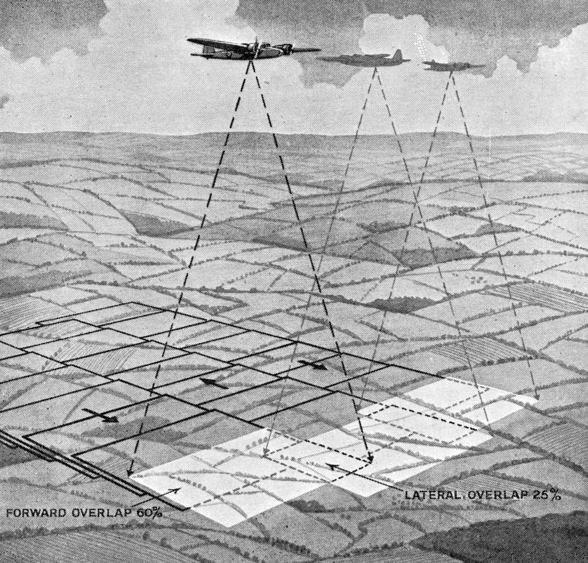
MAPPING
FROM THE AIR
Fig. 13.
Diagram illustrating how a series of successive vertical photographs is
taken from the air for map-making purposes. The aircraft flies at a
consistent height up and down the area of country to be mapped and each
exposure overlaps the previous one by 60 per cent. The lateral overlap,
as shown, is 25 per cent. A “mosaic” is then pieced up
The strategic and tactical requirements of the
Royal Navy and the Army make heavy demands upon the air photographer.
Aircraft are the eyes of all the Services and the camera is by no means
the least important attribute of the aircraft at their disposal. It is
easy to picture the many objectives, mobile and immobile, of which both
the Royal Navy and the Army can by air photography obtain speedy,
accurate and vital information.
Quite
independently, and within
the Air Force itself, air photography plays a most important part in
obtaining information on which are based plans for the utilization of
its striking power with the utmost efficiency and economy in effort.
Happy indeed is the bomb aimer who, from previous study of air
photographs of his targets, knows that from whatever direction he may
approach them he will have no difficulty in identifying them, and so
ensure that his efforts achieve maximum efiiciency. Information gained
from air photographs as to the locations, strengths and types of enemy
air forces assists in the most efficient disposition and employment of
our own air forces, both fighter and bomber, to forestall or counter the
air effort of the enemy, and so attain essential air superiority.
All
bomber aircraft carry a camera with the object of recording
photographically the place where the bombs have fallen. It is quite
simple to do this by day, and a high standard of air photography in
daylight was reached even during the last war. Recently, however, the
art of night photography has been developed so successfully that it can
be regarded as one of the principal means of ascertaining the
effectiveness of the bomber’s work (Fig. 14). As soon as the bombs are
released the camera shutter is opened. The ground is, however, dark and
nothing is recorded on the film except possibly the flashes caused by
anti-aircraft gunfire or the glow of fires already burning in the target
area. The bomb aimer then releases a flash-bomb which has a time fuse
allowing it to fall a certain distance before it explodes, giving a
flash of tremendous brilliance. The release of this flash-bomb is timed
so that it will give its flash a few seconds after the bombs have
exploded, thus recording on the film a picture of the ground which will
include the smoke of the bomb bursts. Immediately after the flash the
shutter is closed. From this photograph the exact place at which the
bombs have fallen can be accurately plotted. In the latest cameras
carried by British aircraft the whole of this process is automatic and
is operated by the bomb aimer pressing a button immediately after the
bombs have been released.
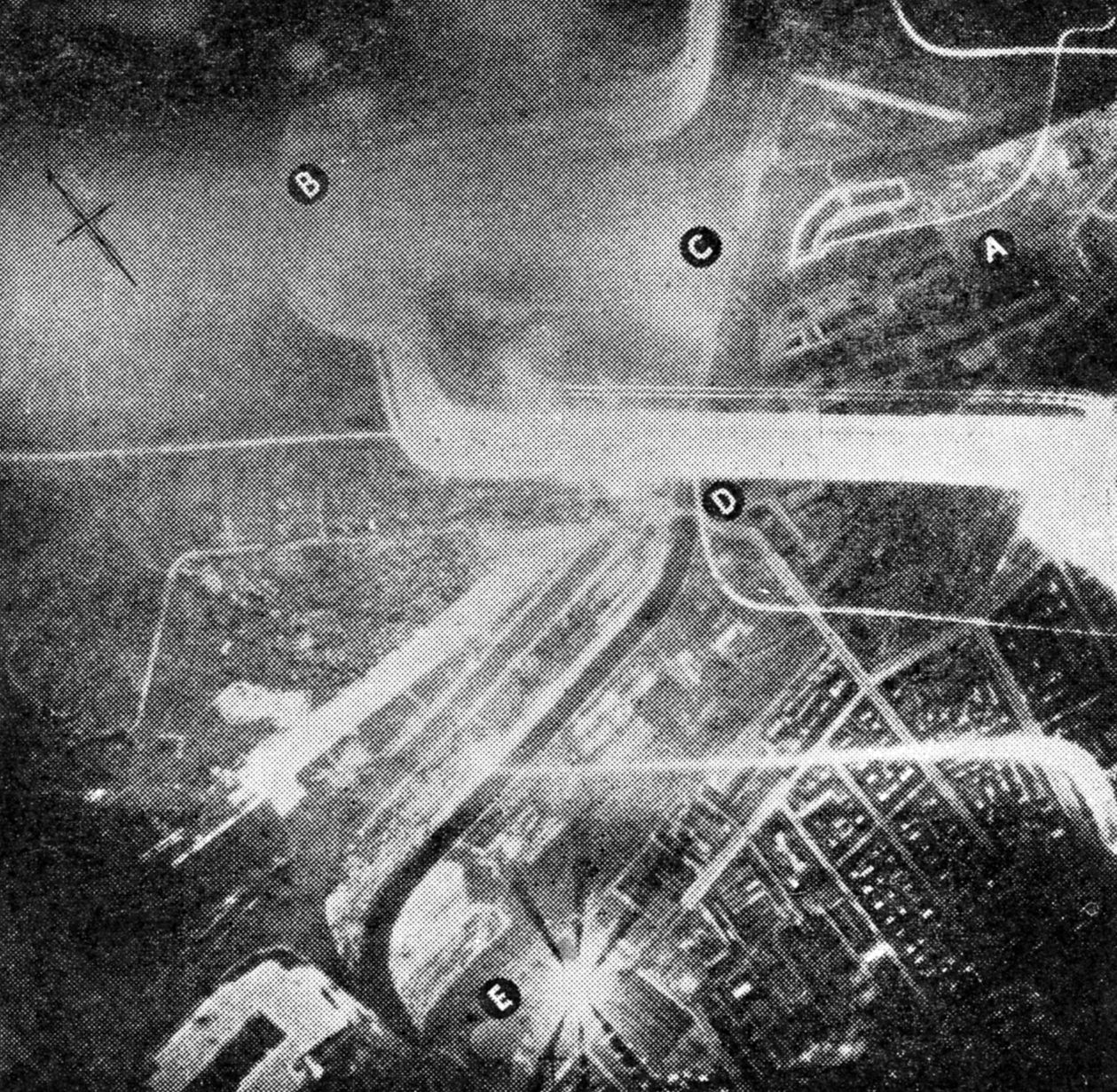
BERLIN
SEEN BY THE NIGHT CAMERA
Fig. 14. This photograph was taken with
a night camera in conjunction with a flash bomb during a raid on Berlin.
The letters indicate: A,
the west harbour; B,
Spandau ship canal; C,
bombs bursting on inner harbour; D,
Konigs Damm bridge and E,
Charlottenburg gas holders. The broad streaks of light are
searchlights, the narrow ones tracer shells
CAMERA GUNS
Nor
would any reference to the value of photography to our Air Force be
complete without a brief mention of the part it plays in the
preliminary training of its personnel in other activities. In his early
training the fighter pilot armed with a camera gun takes a photograph of
his mock adversary instead of firing a bullet at him (Fig. 15); the
bomber pilot photographs his objective in early training instead of
dropping a bomb on it. From calculations based on the position of the
image of the opposing aircraft or the bombing objective on the
negative, it can readily be ascertained whether the bullet or bomb
would have reached its mark and the nature and extent of any error
determined.
CAMERA
GUN IN ACTION
Fig. 15.
During their early training pilots and air gunners are taught to
photograph their mock adversary instead of firing at it. Above, the
camera gun is seen in use with, inset, a developed photograph showing a
“direct hit.” A similar device is used for practice bombing
It
is obvious also that air photographs taken at home give an indication
of how much will be revealed to the enemy of potential objectives
should he carry out a photographic reconnaissance of them.
It
will therefore doubtless be agreed that by whatever Service it is
employed and into whatever sphere the information so gained is
directed, air photographic reconnaissance plays a most vital part in
gaining that knowledge which must result in strengthening our whole war
effort (Fig. 16).
BREMEN
BEFORE AND AFTER A RAID
Fig. 16.
Damage to Bremen discovered by the camera. The letters in the top
picture show buildings before, and in the bottom picture, after the
raid. A. Large shed completely
destroyed. B. Eight bays of another shed
destroyed. C and D. Two other large sheds on which
direct hits have been obtained. E. Four bays of another shed, and
two smaller buildings destroyed
The
training of the air photographer in whatever capacity he may be
employed must of necessity be thorough. One oversight, one mistake, and
a vital piece of knowledge which may have far-reaching
consequences is lost and effort proportionately weakened. The speed and
accuracy which are demanded in the execution of all operational duties
are therefore the keynotes of the training of the air photographer of
whatever the category to which he belongs.
The flying personnel
who may be selected for photographic duties are those who, in their
normal air training have shown special qualifications in navigation and
airmanship and also possess a very keen sense of initiative which will
ensure that, whatever obstacles be encountered, nothing will deter them
from their primary task of securing and delivering the required
photographs.
PRACTICE FLIGHTS
A
thorough knowledge of the working and manipulation of the photographic
apparatus carried in the aircraft, cameras, sights, mountings, etc., is
gained either at an appropriate training establishment or from the
photographic instructor at a squadron, according to circumstances.
Practice flights of progressive difficulty for single photographs, line
overlaps and “mosaics” are carried out, and faults and remedies pointed
out. A sufficient appreciation of the work of the technical and
interpretation personnel must be gained so that, as far as possible,
the flying procedure adopted may facilitate their subsequent work.
Trainees for ground technical duties may be either boy entrants who
undergo a long ab initio
course both theoretical and practical, or specially enlisted
aircraftmen who have had previous experience of commercial photography
in civil life. Whatever the capabilities of the recruits there is much
to learn and unlearn in acquiring the essential knowledge of the
special apparatus and methods which are best adapted to the
requirements of a modern air force.
The interpretation
personnel are selected as far as possible from men who have had
previous experience in air photography. Quick perception, an eye for
detail, and a logical mind are basic attributes.
Though the work
is hard, there is no lack of applicants for this interesting pursuit,
the more so as most posts carry commissioned rank on account of their
onerous responsibilities.
Trained personnel are supplied by the R.A.F. School of Photography, or
other appropriate training establishment.
However
proud we may be of the wonderful achievements of our air photographers,
it would be idle to pretend that finality has yet been reached in the
design of apparatus, mechanically or optically, in technical processes
or in the ancillary instruments and materials, all being necessary for
efficient work.
The research laboratories, service and civilian,
national and allied, are continuously working on the problems,
mechanical, optical and chemical, the solution of which will most
certainly increase the usefulness of photography from the air.
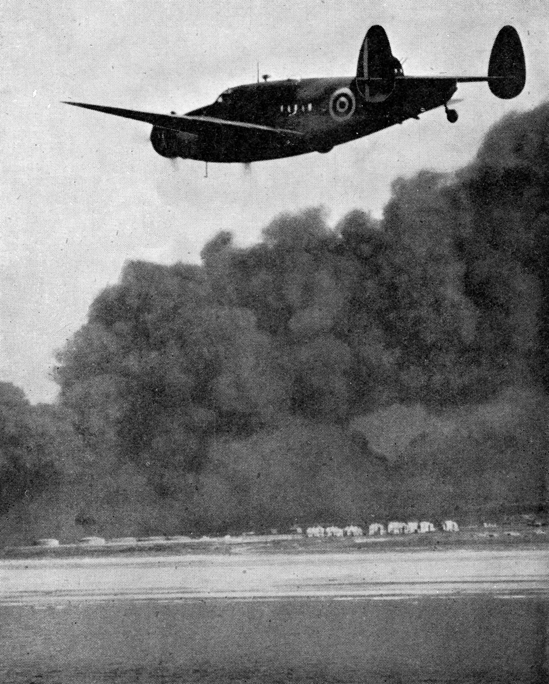
HUDSON
OVER DUNKIRK
Fig. 1.
The Lockheed Hudson, the military version of the Lockheed Fourteen
commercial aeroplane, has done considerable duty with Coastal Command
as a long range reconnaissance bomber. It has a range of 2,000 miles
and has a rotating gun turret fitted to the upper part of the fuselage.
The Hudson above is on patrol duty over Dunkirk at the time of the
evacuation
CHAPTER
13
American
Help for the R.A.F.
Effect
of Lease and Lend Act. British influence on U.S. design. The Lockheed
Hudson and the Harvard trainer. Lightning twin-engined fighter. Wright
turbo-supercharger. Flying Fortress. Tricycle undercarriage. Havoc
night fighter. Bell Airacobra. Liberator bomber. Catalina flying-boat.
American dive bombers. Training of R.A.F. pilots in the U.S.A. The
Eagle Squadron. What American aid means
THIS
chapter has nothing to do with the entry of the United States of
America into the war at the end of 1941. It is concerned only with the
very considerable help given to the R.A.F. by the United
States
manufacturers of aircraft and aircraft equipment before America began
actual fighting; how that help was provided and how the interchange of
information and Britain’s contribution of the store of knowledge she
accumulated with every stage of the development of the war gave a
tremendous impetus to technical advancement.
ANGLO-AMERICAN CO-OPERATION
Today
the United States is still providing Britain with aircraft, though she
has her own services to equip. For certain classes of work the R.A.F.
relies entirely on American machines, while American pilots likewise fly
British types. The Spitfire, with which some American fighter squadrons
are equipped, is perhaps the outstanding example. The two countries are
fighting as one. Their production of aircraft, engines and equipment is
organized as a whole. But when the war began it was not so and this is
the story of how American help started, developed and finally became one
of the dominating factors in turning the tide of the air operations.
When
the United States first set out to supply aeroplanes to the R.A.F.,
Britain had to take what could be spared. At that time the purchaser
had both “to pay on the nail” for everything he chose and to do the
transporting himself. Britain placed quite large orders under that
arrangement, but in March 1941 the Lease and Lend Act was passed by the
United States Legislature. That meant that the R.A.F. could have more
aeroplanes than it could pay for.
At the end of May President
Roosevelt pledged the United States to see that the weapons of war from
America should reach the democracies; and that meant that American
ships could carry some of the goods and that, if necessary, American
warships would convoy them. To British self-help had been added the
promise of the generous help America could give.
GUIDANCE FROM BRITAIN
These
stages are worth considering as a prelude to estimating the American
contribution to Britain’s war effort, not only because they explain the
growing momentum of the American aid but also because they are
significant of British influence in guiding that aid along paths parallel
with those which were being followed in Great Britain. Mere numbers
alone would not necessarily have assured the R.A.F. of air
superiority. In the Battle of Britain, an enormous advantage in numbers
availed the Germans little. Superior quality in men and machines
enabled the R.A.F. to throw back the German hordes with tremendous
losses. If America had simply flooded the R.A.F. with aircraft of
inferior performance and armament, Britain might equally have found
herself in the unhappy position of having the numbers but not the
strength.
INFLUENCE ON U.S. DESIGN
Some
such situation might have arisen if, from the start, the U.S.A. had
been handing out largesse to the British. The easy way would have been
to go full speed ahead with the types which were already in production.
Up to a point the British had to accept that method because of the
urgency of their need, but the important point was that they were
paying for what they got and were therefore in a position to require
modifications here, more armour there, and guns in different positions.
Furthermore, within the limits set by considerations of early delivery,
Britain could pick this type and reject that. The result was that she
began to direct American development along particular lines and
stimulated the production of certain types.
The independence
that Britain gained in those early months was well worth the huge sums
she undertook to pay the American manufacturers, since it meant that
her specifications were accepted and her views on the types of aeroplane
best suited to modern warfare became established.
A trend was
established by the British requirements in the early days that
influenced American fashions. As an example of this one need only recall
that arrangements were made for the Rolls Royce Merlin engine to be
built in America. Production and delivery are now in full
swing.
Already a water-cooled engine, the Allison, had been produced there,
and so a nation which had previously relied on air-cooled engines began
think in terms of the slimmer lines and higher speeds which the small
frontal area of the liquid-cooled engine permits.
PRE-WAR PURCHASES
Even
before the war the British had been buying Hudsons (Fig. 1 above) for
reconnaissance work and Harvards (Fig. 2) for advanced training. Both
aircraft in improved forms are still being delivered for use by the
R.A.F. The Hudson was the commercial aeroplane known as the Lockheed
Fourteen, so modified that a rotating gun turret could be fitted on the
upper part of the fuselage just forward of the tail. The North American
Harvard was a fast, single-engined trainer.
HARVARD
ADVANCED TRAINERS
Fig. 2.
North American Harvards play a leading part in the training of fighter
pilots for the R.A.F. They are easily recognized by the fully tapered
leading edges of their wings, and their distinctive and harsh engine
note which sounds somewhat like a two-stroke motor cycle
For
a long time the British asked for nothing more, but the French, whose
aircraft industry had been shamefully neglected, had been buying much
more freely. They had taken delivery of a good many Curtiss Hawk
fighters. They were hoping, when the German advance crushed them, to
receive aircraft of at least four other types from America. These were
the Vought-Sikorsky 156 dive bomber, the Martin 167 twin-engined
bomber, the Douglas DB-7 twin-engined bomber and the great Consolidated
Model 32, which is a four-engined bomber of a loaded weight of more
than eighteen tons and a top speed of 335 miles per hour. It is known
in the R.A.F. as the “Liberator” bomber.
When Great Britain
found herself standing alone against the Germans in June, 1940, she was
able to arrange to take over these orders and so to profit by
the
time which had already been devoted to them. The Hawk passed into the
R.A.F. in slightly modified form as the Mohawk. The others were named
the Martin Maryland, the Douglas Boston and the Consolidated Liberator.
The Vought-Sikorsky was named the Chesapeake and passed into service
with the Fleet Air Arm.
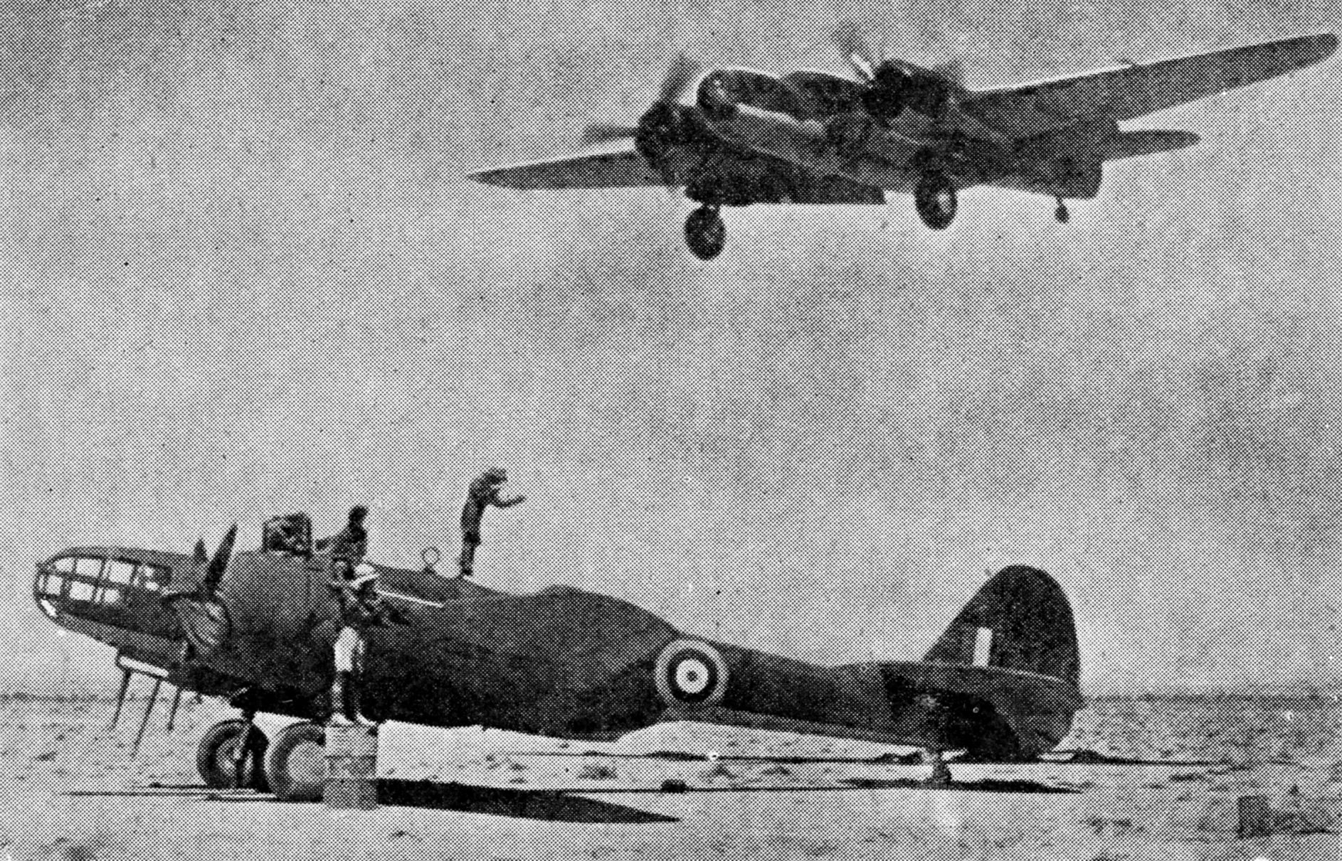
MARYLANDS
IN THE MIDDLE EAST
Fig. 3.
Martin Maryland twin-engine bombers first proved their worth in the
Middle East where they were first in service in November, 1940. They
also took photographs which led to the Fleet Air Arm attack at Taranto.
Above, two machines of a Maryland squadron are seen on active service
in the desert. They have a top speed in the neighbourhood of 320 m.p.h.
During
the succeeding six months the British Purchasing Commission worked so
hard that more than thirty different types of American aeroplanes were
being built for the R.A.F. Among them were ten fighters, seven bombers,
six reconnaissance types including flying-boats and three types suitable
for service in aircraft carriers with the Fleet Air Arm. By the
beginning of 1941 many were flowing in large numbers into R.A.F. units
in Britain and overseas. The Marylands, for instance, were in service
in the Middle East as early as November, 1940 (Fig. 3). They took the
photographs which led to the great Fleet Air Arm attack on ships of the
Italian Navy in Taranto harbour and returned afterwards to get pictures
of the damage done by torpedo bombers of the Fleet Air Arm. Tomahawk
fighters (Fig. 4) were first reported in action during attacks on German
aeroplanes using aerodromes in Syria in the latter part of May, 1941.
Before that, Bostons had taken part in bombing raids from Great Britain
and the Havoc, the night fighter version of the Boston, had begun to
destroy German bombers.
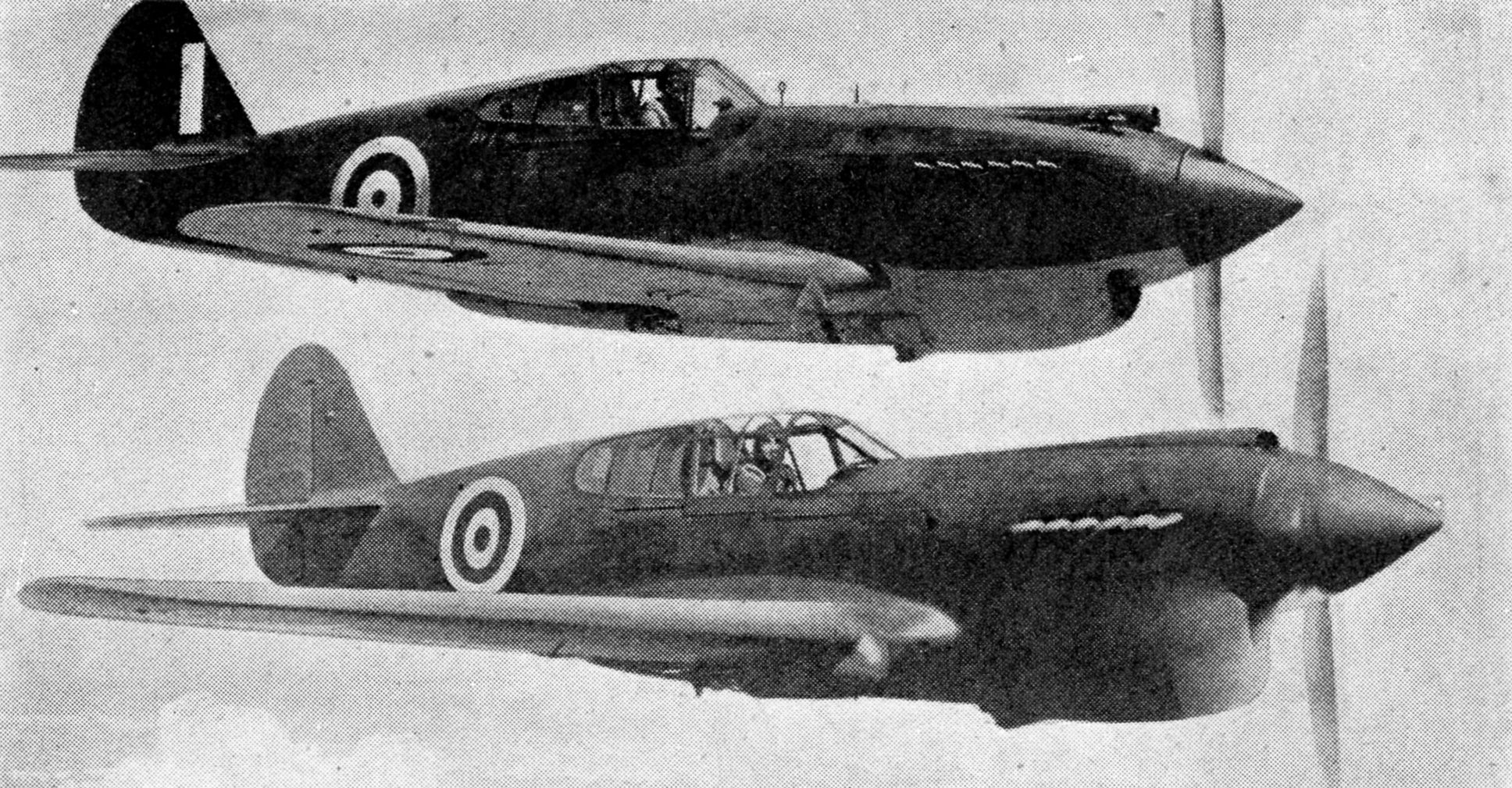
TOMAHAWK
AND KITTYHAWK
Fig. 4.
The Curtiss Tomahawk fighter (above), like the Maryland, was first used
operationally in the Middle East. It is extremely fast and manoeuvrable
and is the American counterpart of the Hurricane, which it closely
resembles. The Kittyhawk (below), is an improved version of the
Tomahawk, and it has a maximum speed of about 380 m.p.h.
LEADING
TYPES OF AMERICAN AIRCRAFT IN SERVICE WITH THE R.A.F.
Engine
particulars and maximum speeds of thirteen types of U.S. aircraft
employed by the R.A.F. Many of these incorporate new ideas in aircraft
design such as the tricycle undercarriage which is fitted to the
Lightning and Airacobra fighters and the Boston and Liberator bombers.
The Lightning and the Airacobra are also unusual, the former in having
a split fuselage and the latter in having the engine behind the pilot.
Both have a top speed of about 400 m.p.h. The Catalina reconnaissance
flying-boat is remarkable chiefly for its very long range
BRITISH TECHNICAL ADVICE
Operational
and technical advice was invited by American manufacturers. In
response, Air Chief Marshal Sir Hugh Dowding, who had formerly
commanded Fighter Command, led a mission which remained for many months
in the United States. British technical men were admitted to the works
of the principal aircraft firms. The rapid results of all these
forms of contact were almost startling and they quickly became
apparent.
Firms
which had previously given the scantiest attention to protecting the
vital parts of their aeroplanes from damage by machine gun and
anti-aircraft fire now produced in remarkably short time bombers and
fighters which had better protection for fuel tanks and pilots than was
to be found even in the aeroplanes with which Britain entered the war.
They
were typical of the advantages which accrued to the R.A.F. from the
readiness of Great Britain to “pay the piper,” and of the consequent
willingness of most American manufacturers to allow the British, up to
a point, to “call the tune.” The British for their part were only too
happy to give all the help they could. A Messerschmitt 110 twin-engined
fighter was even shipped across to the United States for examination by
American aeronautical engineers so that the best available examples of
modern practice on both sides of the war front might be at the disposal
of those who had undertaken to build for the R.A.F. out of range of the
enemy’s bombers.
LOCKHEED LIGHTNING
The
Lockheed Company promptly set itself to produce the P.38 twin-engined
fighter (Figs. 5 and 6). It is known as the Lightning, and its speed,
according to manufacturers’ reports, is just over 400 miles per hour.
It did not see service with the R.A.F. however, as the United States
entered the war before it was fully in production. It is now being used
by the U.S. Army Air Force. The Douglas Company, for its part, set out
to produce a more capacious bomber than anybody had yet contemplated
using in war. It designed a huge machine of a loaded weight of
seventy-three tons.
LOCKHEED LIGHTNING
Fig. 5.
The Lockheed P-38 fighter is a high speed twin-engine aircraft of
unusual design. The tail unit is carried on two booms and the central
nacelle accommodates the pilot and the armament. The P-38E is a
two-seat version of the same machine
DETAILS OF THE LIGHTNING
Fig. 6.
Principal parts of the Lightning. This machine has a range of about
1,000 miles and a top speed of more than 400 miles per hour. It is
fitted with a tricycle undercarriage and armed with four machine guns
and a 23-mm. Madsen shell firing gun firing through the nose
Before the war, the Boeing Company was
engaged in producing what it called the Stratoliner, a commercial
aeroplane with a hermetically sealed cabin in which the air pressure
was to be kept much higher than that in which the aeroplane was flying.
The intention was to obtain the speed advantages which come from flying
in the thin air at great heights without causing the discomfort which
passengers normally suffer from reduced pressure and shortage of
oxygen. The Stratoliner was not really supposed to fly in the
stratosphere. It was to cruise at heights between 20,000 and 30,000
feet, but to preserve in the passenger cabin an air pressure roughly
corresponding to that at 10,000 feet.
The Wright Corporation
having provided the supercharged Cyclone engines for the Stratoliner
continued its experiments with still more efficient superchargers. For
some years engine designers have been examining the possibility of
harnessing the wasted energy from engine exhausts to the task of
driving superchargers. The gases, as they emerge from the
exhausts, possess a large store of energy. This, it had been hoped to
apply on the ordinary turbine principle to a piece of special apparatus
which in turn would drive the impeller or fan attached to the
supercharger (Fig. 7).
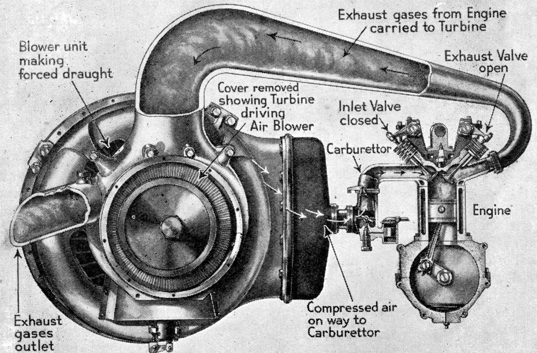
PRINCIPLE OF THE TURBO-SUPERCHARGER
Fig. 7.
Diagram illustrating how the exhaust gases from the engine can be used
to drive the supercharger. Turbo-superchargers are embodied in Wright
Cyclone engines such as are fitted to Boeing Flying Fortress bombers,
and permit the engine to give unusually high power at heights where
ordinarily supercharged engines are giving only a fraction of their
rated output
TURBO-SUPERCHARGER
One
awkward matter had been to find a metallic substance for the turbine
blades which could withstand the extremely high temperatures of the
exhaust gases. At last the Wright engineers met with success, for the
engine which was used originally in the Stratoliner has now appeared
for use in military aeroplanes with a turbo-supercharger. This
permits the Cyclone engine to give unusually high power at heights
where ordinarily supercharged engines are giving only a fraction of
their “rated” output. The Boeing Company, having stimulated work in
this direction, was the first firm of aircraft constructors to reap the
benefit of this new supercharger.
Out of the Boeing Company’s
works in 1935 had come the big four-engined bomber described by the
United States Army Air Corps as the B .17, and popularly known as the
Flying Fortress. In its early form the Flying Fortress, operating at a
loaded weight of twenty-two tons, developed a top speed of 250 miles
per hour at a height of 13,000 feet. It has undergone various
modifications since war broke out. By far the most important of them was
the fitting of the new Cyclone engines. With this type of engine, the
new Flying Fortress, or B. 17c, as it is officially known, can carry the
same load and develop a top speed of 325 miles per hour at a height of
20,000 feet, and is rated for cruising at a speed of 245 miles per hour
at 30,000 feet. Bombers of this kind have made many daylight raids with
outstanding success on enemy objectives from great heights (Fig. 8).
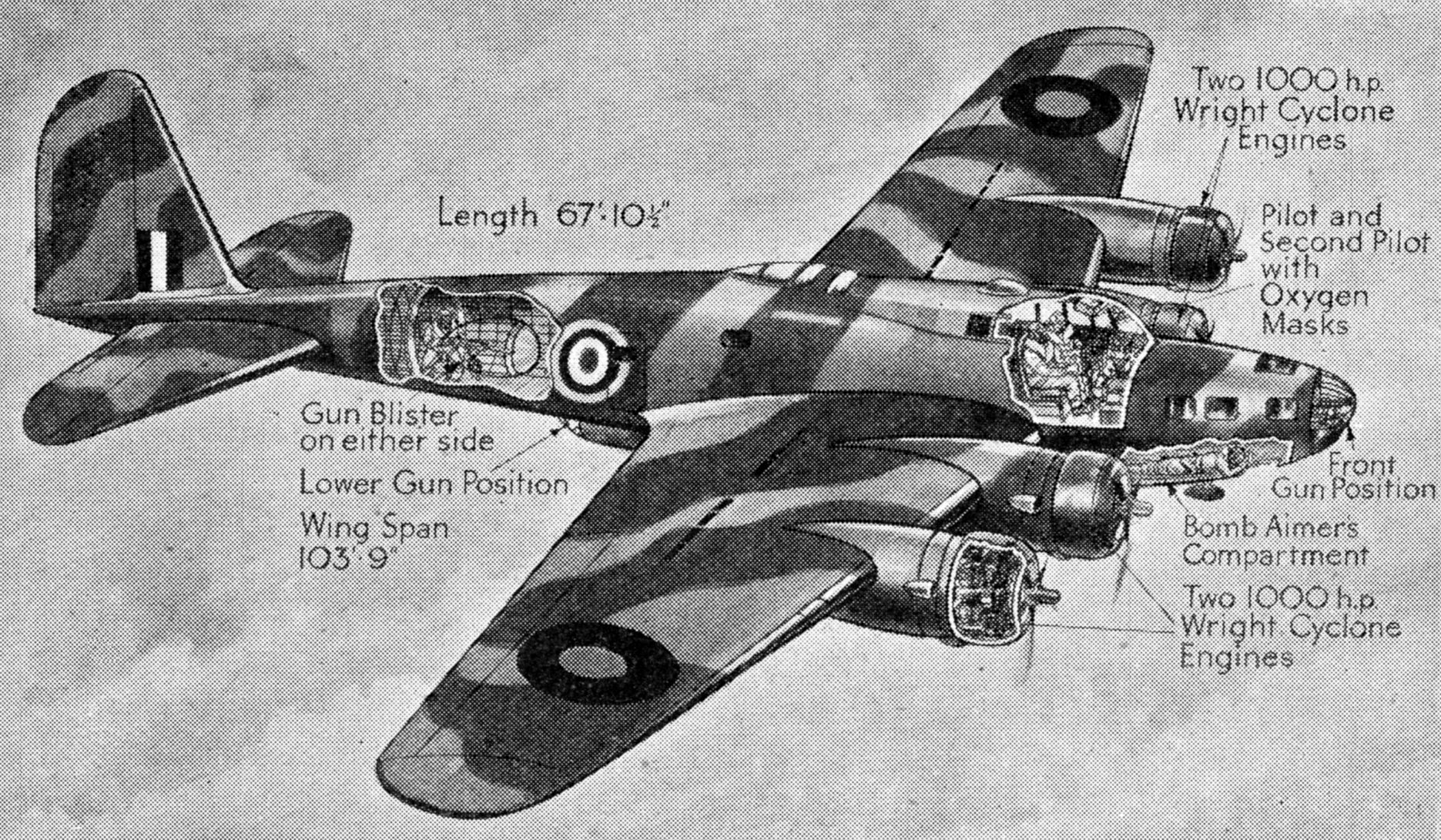
THE BOEING FLYING FORTRESS
Fig. 8.
Known in the U.S. as the B.17C, these machines are equipped with Wright
Cyclone engines embodying the turbo-supercharger. They have an
exceptionally high service ceiling and can carry a bomb load of about
four tons. Their top speed is about 325 m.p.h. at 20,000 feet
“RATED HEIGHT”
No
other aeroplane in the world has such a high “rated height.” Many
aeroplanes of course can fly at heights above 30,000 feet, but the
“rated height” of most military aeroplanes is somewhere between 15,000
and 20,000 feet. The “rated height” is that at which the best
combination of speed and load can be obtained. It depends almost wholly
on the degree of supercharging which can be given to the
engine or
engines. The “rated height” of the Spitfire fighter, for instance, is
17,000 feet, whereas its “service ceiling”—the height at which it is
still capable of climbing at the rate of 100 feet per minute—is well
over 30,000 feet.
The
benefit to be derived from increasing the height at which the bombers
can fly is obvious to all who examine the question of interception by
enemy fighters. If the fighters have to climb to great heights to cut off
the bombers, there is a fair chance that the raiders may have reached
their targets before they can be attacked. Flying high, the bombers may
be out of range of the anti-aircraft guns. In certain circumstances
they may escape detection altogether. They may get above the
“smoke-trail”
forming layer of the atmosphere. Also, of course, as sound takes time
to travel, great height causes confusion to the ground defences.
Aircraft flying fast at a great height will be well in advance of the
apparent location of the noise they make. Height indeed is one of the
most valuable attributes in air warfare, and in these days of highly
accurate bomb sights, it may be no serious deterrent to accurate
bombing either in daylight or clear weather.
TRICYCLE UNDERCARRIAGE
There
was another form of aeronautical advance in which the United States had
“taken a chance.” It had pushed on with the application of the tricycle
undercarriage. Some experiments had been made with the new combination
of wheels in Great Britain, but whereas the British came slowly and
cautiously to this development, the aircraft industry in the United
States took its courage in both hands and applied the new idea to quite
massive aeroplanes. The Boston twin-engined bomber, weighing some seven
and a half tons fully loaded, had a front wheel instead of a tail
wheel, from the start. The Liberator, the big four-engined bomber of a
loaded weight of eighteen tons, was born, so to speak, with a tricycle
undercarriage. The Liberator, by the way, in addition to being used by
the U.S. Army for daylight raids, is doing valiant service with the
British Coastal Command in the Battle of the Atlantic.
In the
end this improvement may prove to have been a good thing. In the early
stages, R.A.F. pilots had a certain amount of trouble with the nose
wheel. It did not behave well on soft, muddy surfaces, and there was a
period at which the front wheel developed the form of wobble known as
“shimmying.” A certain amount of modification had to be done, and during
the interval, British pilots acquired the habit of landing on the two
main wheels and of using the front wheel simply as a safeguard against
“nosing over,” when the brakes were firmly applied. The device has thus
come to serve one of the principal purposes for which it was intended,
and it is well on the way towards fulfilling all the other hopes that
were reposed on it.
CONTROL IN LANDING
The
arguments in favour of the nose wheel are that it helps the take-off by
enabling the pilot to start his run with the aeroplane in the flying
attitude, that it makes control on the ground easier if there is a
steerable wheel in the front, and that landings are simpler because the
aeroplane need not be stalled on to the ground and the landing run
shorter because the brakes can be put on hard as soon as the wheels
touchdown. These are important matters with fast landing speeds and
heavy overloads at take-off.
AN UNORTHODOX AMERICAN FIGHTER
Fig. 9.
The Bell Airacobra, the principal features of which are illustrated
above, is a single-seat fighter with a credited speed of over 400 miles
per hour. The engine is placed behind the pilot with a shaft to drive
the airscrew running between his legs. Its powerful armament consists
of one cannon and four machine guns synchronised to fire through the
airscrew
One of the most useful of the night
fighters, the Havoc, is fitted with a tricycle undercarriage. This
machine is the fighter variant of the Boston and has been operating
successfully as a night fighter since the early part of 1941. Another
United States fighter which also uses the nose wheel embodies various
other novel ideas besides. This is the Bell Airacobra (Fig. 9), a
single-engined machine of a top speed of about 400 miles per hour. It
is fitted with the new Allison liquid-cooled engine. This is set behind
the pilot and drives the airscrew by means of a long shaft
which
passes between the pilot’s feet to a set of gears arranged to transmit
the power to a shorter shaft driving the airscrew. By way of final
complication, a 37-mm. cannon is placed to fire through the airscrew
hub. A British fighter squadron engaged in low level attacks on targets
in Northern France and Channel shipping was equipped with the Airacobra
towards the end of 1941, but the machine was later superseded by
another type.
CATALINA FLYING BOAT
Bearing in mind the fact that
the R.A.F. began the war without enough machines in any category, those
who look into the matter will realize how valuable some of the American
help proved. One of the first machines to be delivered to the R.A.F.
from the United States was the Catalina flying-boat,
the military version of the Guba
civil flying-boat* which made a survey
flight just before the war across the Indian Ocean from Australia to
Africa, calling at small islands on the way. That flying-boat is
supposed to have a range of 4,000 miles. During the week in which the
German battleship Bismarck
was shadowed in May, 1941, one Catalina
remained on patrol for twenty-seven hours and must have flown 3,500
miles in the course of that tour of duty.
*The trans-ocean flights
of the Guba
are described in the book The
Sky Beyond,
written after the war by the aircraft's captain, Sir Gordon Taylor.
The R.A.F. had no
other flying-boat capable of such endurance. The normal range of the
Sunderland, the four-engined British flying-boat is 1,780 miles. The
two craft are not strictly comparable of course. The Sunderland is
faster, is better armed for self-defence and better armoured for
protection. It has much greater capacity. In brief, it was built for an
entirely different class of work in the relatively narrow seas, whereas
the Catalina, or PBY. 5 as the United States Navy calls it, was built
for ocean work. A Catalina could fly 1,000 miles westwards over the
Atlantic to meet a convoy, could remain cruising protectively in its
vicinity for ten hours, and then could fly back to its base without
having exhausted its supply of fuel. That was the sort of thing the
Coastal Command badly needed when German occupation of France and
Norway enabled her to spread her submarine operations over a
coastline which was too long for the Navy to watch closely. The
Catalinas came at the right time and fitted admirably into a vacant
place. They are illustrated in Chapter 8.
America’s chief
advance in aircraft technique concerned the production of long range,
weight-carrying machines, the day bombers such as the Fortresses,
Liberators (Fig. 10), the transports and the flying boats. Britain,
having begun the war on the defensive, had to rely to a great extent on
fighters. She therefore developed the fighter more rapidly and then
concentrated on the night bomber such as the Halifax and Lancaster.
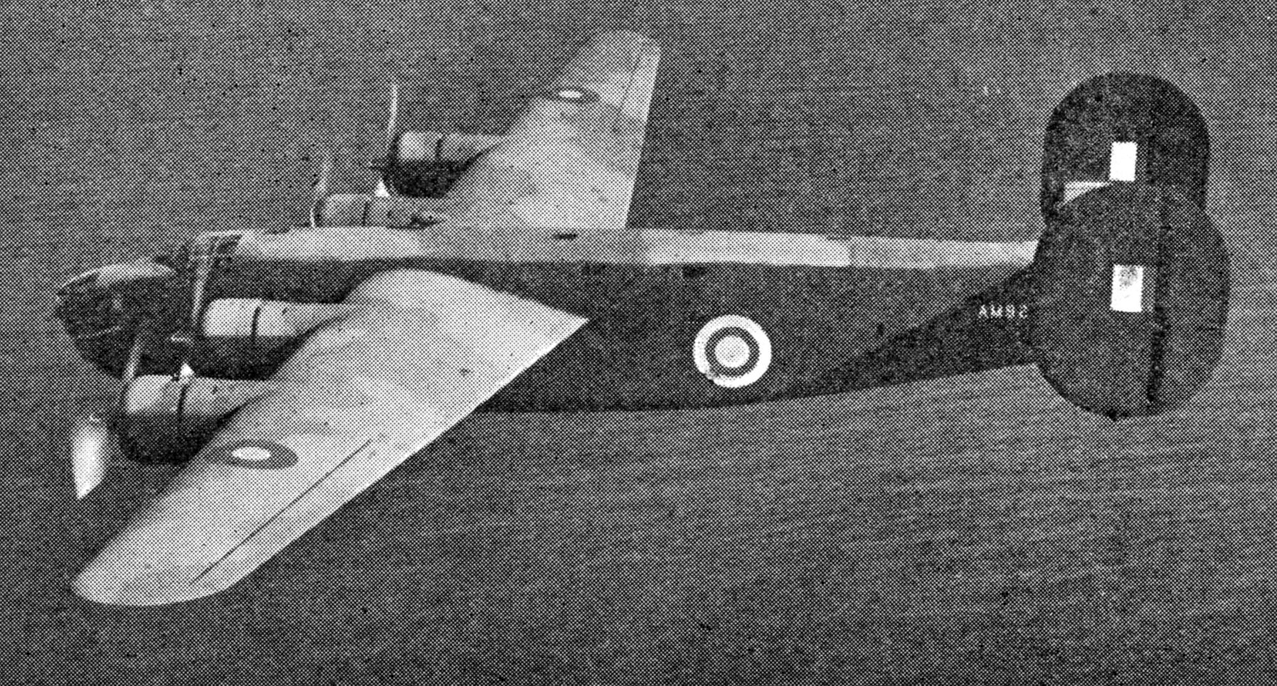
CONSOLIDATED LIBERATOR BOMBER
Fig. 10.
The Liberator, illustrated above, was the first of the big bombers to be
flown direct to Britain. It has a range of 3,000 miles and an
exceptional top speed of 335 miles per hour
DIVE-BOMBERS
But there was one type of aircraft to which America paid attention
almost alone, the dive-bomber. Britain left dive-bombers out of her
early calculations for the simple reason that their use by the Germans
had proved that they were ineffective except where there was complete
air dominance and that they only had a tactical advantage, not a
strategic. Britain, first of all, had to get air dominance by means of
fighters and she then found that fighter-bombers, such as the Hurricane
and Whirlwind, could be used in many cases more effectively than
dive-bombers. Today, however, two dive bombers are being produced by
the United States for the R.A.F., the Bermuda and Vengeance, but how or
where they are being used cannot yet be disclosed.
The old Curtis “Helldiver” of 1937 will be remembered, for it received
a good deal of publicity. It is an obsolete model, though its
performance was nearly as good as that of the Junkers 87 (the Stuka)
which the Germans used largely in Poland and France. Great Britain
produced one dive bomber, the Blackburn Skua, especially for the Fleet
Air Arm. The Vengeance in particular is a vast improvement on either
the “Helldiver” or the Skua and is now reported to have overcome its
various “teething” troubles most satisfactorily.
Several large firms in the United States agreed to share with one
another the task of turning out quantities of the types the R.A.F.
particularly needed quickly or in great numbers. As one outstanding
example there was the agreement of the Boeing, Douglas and Lockheed
concerns to co-operate in the building of Fortresses, the high flying
bombers. A joint effort on a rather smaller scale was that of the
Vultee and the Northrop Companies to turn out the Vultee Vengeance at a
high rate. In addition, sections of the motor car industry were turned
on to aeronautical work, and huge new factories were set up
and equipped with machinery at an amazing rate. The famous Packard firm
is manufacturing the Rolls Royce Merlin engine and Ford’s have erected
the world’s largest aeroplane plant at Willow Run for the production of
Liberators.
On the industrial side, the expansion of manufacturing capacity was
great and rapid. One of the best signs of the rate at which aeroplanes
were being turned out was to be found in engine production. Before the
United States began building for the R.A.F. the average monthly output
of aero-engines stood at 200 to 300 a month. By the end of May, 1942,
the rate of production had risen to 15,000 a month, and this has
advanced steadily ever since. That represented a total of more than
5,000 aeroplanes, some of which were wanted by the United States for
her own air services, but reports showed that the R.A.F. received
something exceeding half up to the time when help was extended to
Russia.
Delivery of the goods has naturally been as important as making them,
and in this respect too the United States gave help in an ascending
scale. When the Lease and Lend Act had been passed, British crews were
allowed to collect aeroplanes from the makers’ works and to fly them to
Newfoundland and Canada on their way to the European front. Until Japan
entered the war others were flown from the Pacific coast to Hong Kong and
Malaya.
The United States, as a measure of self-defence, established air and
naval patrols over the western waters of the Atlantic. When enemy
vessels were sighted, she broadcast the information for the benefit of
all shipping in the vicinity. Later, after German attacks on several
U.S. ships, she announced that her navy would protect all Lease-Lend
cargoes between America and Iceland.
Another important factor was the decision of President Roosevelt that,
after the defeat of the Italians in Eritrea and Somaliland, the Red Sea
need no longer be regarded as a theatre of war, and American ships need
no longer be excluded from it. Many fighters from the United States were
thereafter delivered by American ships to the R.A.F. in the Middle
East. They began to arrive in time for the big operations over Libya.
How Ferry Command now delivers American supplies of aircraft and
equipment is told in another chapter.
As American opinion hardened against the Germans throughout the summer
of 1941, there was a shrewd suspicion in Great Britain that more would
soon be done by the United States to accelerate and to ensure the
delivery of war material to the R.A.F. That this suspicion was justified
was proved in September, 1941, when the United States decided
to protect Lease-Lend cargoes. One slight token of the spirit of the
United States Government was the decision to put some of its own
Fortresses on a passenger and goods service between America and Great
Britain. Another, of greater significance, was the agreement to train
8,000 R.A.F. pilot pupils at flying schools in the United States during
the year 1941-1942.
Before war between the U.S. and Japan broke out a great many citizens
of the United States had crossed into Canada to enlist, with or without
subterfuge in the R.A.F. One purely American squadron of the R.A.F.,
the Eagle Squadron, first went into action in the summer of 1941. Later
two more Eagle squadrons operated with the R.A.F. until the
entry of the United States into the War resulted in all the pilots
transferring to the U.S. Army Air Corps. Those pilots now wear two
“wings,” the R.A.F. and the U.S.
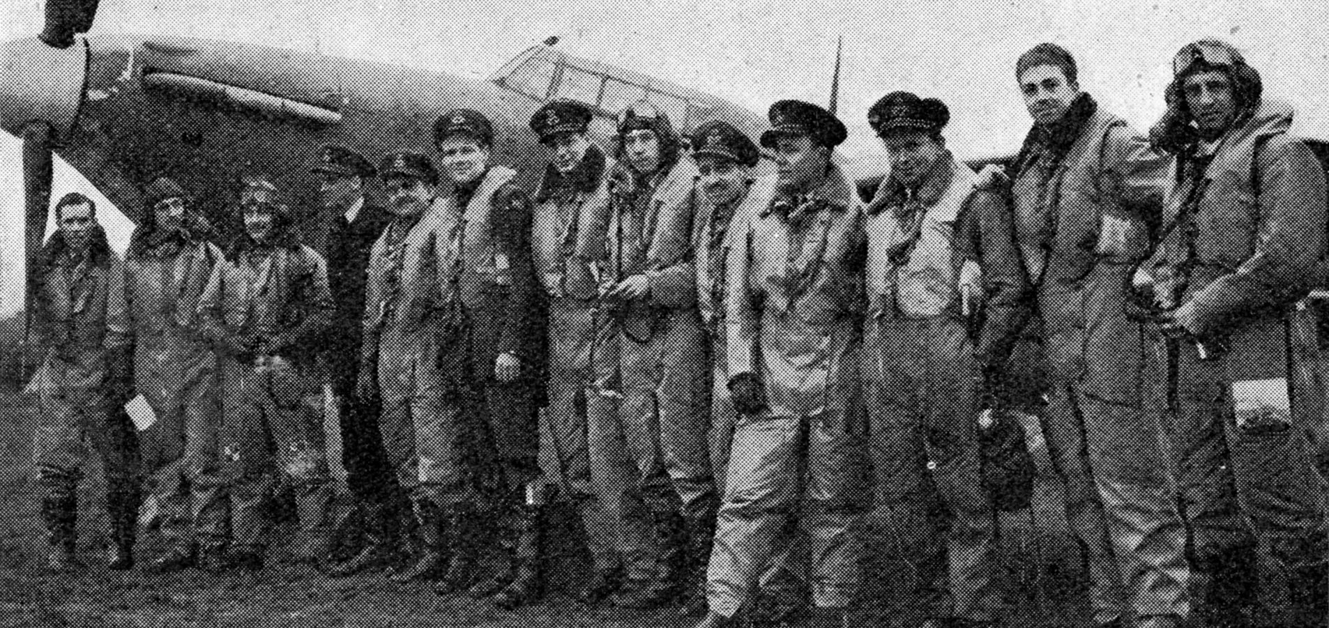
THE EAGLE SQUADRON
Many
citizens of the U.S. enlisted in the R.A.F. and in the summer of 1941
an American squadron, the Eagle squadron, went into action. Some of its
flying members are seen above
THUNDERBOLT FIGHTER
The
Thunderbolt single-seater American fighter in service with the U.S. Army
Air Force in Britain. It is powered by a Pratt and Whitney 2,000 h.p.
engine which will carry it to 40,000 feet and gives a top speed of more
than 400 miles per hour. Its powerful armament consists of eight 0.5
machine guns with a combined rate of fire of 6,400 rounds a minute
Out of the United States, therefore, we have received in a variety of
ways support of good quality and a measure of encouragement which may
truly have emerged from the realist outlook declared by many American
writers to be the mainspring of American actions, or may have been
mixed with a sentimental regard for Great Britain when she
stood alone to face the full power of an over-armed, ruthless and fully
regimented nation of gangsters. Great Britain began well by placing
orders and financing the expansion of the United States Aircraft
Industry to the value of £500,000,000. She received good value
in return, and received it much sooner than she could possibly have
done had she waited for the passing of the Lease and Lend Act.
American aid brought greater striking power to the R.A.F., and greatly
strengthened that force in the Battle of the Atlantic. In short, it
helped Britain to progress from the defensive to the offensive in air
warfare, and gave promise of contributing effectively to the most
massive air offensive that the world has ever seen.

KEEPING TRACK OF ENEMY RAIDERS
Fig. 1.
Plotters at a Royal Observer Corps centre during the Battle of Britain.
They are each connected by telephone to three observer posts, and each
has a tray of counters for plotting the tracks of enemy aircraft.
Overlooking the table, on a raised dais, are the duty crew controller,
and the tellers who pass and receive information from adjacent centres
CHAPTER
14
Weapons
used in Attack and Defence
Royal Observer Corps.
Radiolocation. Control room at a fighter station. Sound locators.
Searchlights. A.A. guns. Balloon barrages. High explosive, incendiary
and gas bombs. Armour-piercing bombs. Fusing of bombs. Magnetic mines.
Aerial torpedoes
THE air defence system in Great Britain is the most highly developed
organization of its kind in the world. Briefly it relies upon: first, a
reporting service; second, fighter aircraft; and third, anti-aircraft
guns and balloon barrages.
ROYAL OBSERVER CORPS
Britain’s secret weapon, “radiolocation,” is one-half of the
reporting system; the Royal Observer Corps is the other. Radiolocation
warns of enemy approach; the duty of the R.O.C. is to keep track of the
movements of the enemy over this country. This information is required
for two main purposes, first to enable fighters to be sent to the right
position to intercept the raiders, and second, to enable air-raid
warnings to be issued to districts in advanceof the direction in which
the raiders are proceeding.
The general system is that of forming a network of observer posts over
the area to be observed and to connect the posts by direct telephone to
centres where track is kept of aircraft movements.
In charge of each post there is a head observer; an observer group
officer with three assistants is responsible for the supervision of each
group of posts.
A centre controller with one assistant looks after the administration,
training and efficiency of his crews; about twenty-five men are on duty
in a centre at a time. A centre with all its associated posts is known
as an observer group and there is an area commandant with two deputies
who take charge of each seven observer groups. The headquarters of the
Royal Observer Corps is at Fighter Command.
In each fighter group operations room there is an R.O.C. liaison officer
always on duty who is in direct telephone communication with every
observer centre within the fighter group area. He receives regular
reports from each one of these centres regarding all events that have
been reported by posts, such as types of aircraft seen, the dropping
of bombs and flares, aircraft in distress and so on. He passes these
immediately to the operations ofiicer or to the intelligence officer in
the fighter group operations room.
R.O.C. CENTRE
At each centre there is a centre room, with a plotting table on which
is fitted a squared map, round which are seated the plotters, each with
a small switchboard connecting him by direct line to three posts (Fig.
1 above). Each plotter has a tray containing distinctive counters
required
for plotting tracks and indicating the number and height of any
aircraft reported. Walking round the table is the table supervisor
watching the tracking, receiving reports from the plotters of
information, other than numbered square plots, given by posts. He
has a supply of various lettered and numbered symbols, from which he
can select the appropriate ones which have to be placed against the
leading plotting counter of each separate track.
Overlooking
the centre table, on a raised dais, are the duty crew controller, the
“teller” passing information to R.A.F. operations rooms, another
“teller” passing to and receiving from adjacent centres various items
of information, telephonists connected both to the Observer Corps
liaison officer at fighter group and to the liaison staff in sector
operations room, and the “recorder” who keeps a record of the tracks
appearing on the centre table. On this dais is also an alarm officer
giving information to selected factories and aerodromes of the
movements of enemy aircraft which pass within range.
In order to
indicate how the whole system operates let us assume that a centre in a
coastal observer group has received information that an enemy raid is
approaching over the sea. The raid is allotted a symbol which the table
supervisor immediately places in a small moveable stand on the edge of
the centre table at the position at which the enemy aircraft are
expected to cross the coast.
OBSERVATION POSTS
The
plotters connected to the coastal posts warn the crews what to expect.
The two men of each post are scanning the sky, No. 1 has set the height
bar (Fig. 2) of one of the instruments used to the height given from
the centre. One of the two makes use of binoculars. When the enemy
aircraft are seen No. 1 estimates their height and readjusts the height
bar, if necessary. He then adjusts the sights until they are on the
aircraft and says “On.” No. 2 looks at the pointer of the instrument
and reports to the centre the appropriate square, the number of
aircraft, their height and their direction of flight. After passing his
message, he amplifies it later by specifying the type of aircraft and
any other information which may be of value. No. 1 keeps his sights on
the aircraft and says “On” at frequent intervals. No. 2 reports
appropriate squares as the pointer of the instrument moves over them.
DUTY CREW AT AN OBSERVER POST
Fig. 2.
Observer posts are manned night and day by two men. No. 1 ascertains
the height of the aircraft by means of the instrument shown above,
while No. 2 makes reports to the centre as to the number of
aircraft, their height, and the direction in which they are flying
The
other two of the three posts which are connected to the same plotter at
the centre overhear these reports and when possible obtain a correct
height which they pass to the plotter at the centre. As the raid
proceeds, the plotter at the centre may order one post to cease
reporting and another nearer one to carry on. When the raid has passed
out of range of the original posts, adjacent posts will have picked it
up and the next plotter at the centre will continue the tracking, and
so on.
WORK OF PLOTTERS
As
soon as a plotter receives a plot he places a counter on the
appropriate square. Alongside he places a numeral counter to indicate
the number of aircraft and another to indicate their height in
thousands of feet. The table supervisor ensures that the raid
symbol is started off at the head of the raid when first plotted and
that it is turned so that it can easily be seen by those on the dais.
Immediately
the first plotting counter is placed on the table the tellers on the
dais begin to “tell” to the R.A.F. operations rooms concerned. In
addition, information is passed over the liaison lines regarding the
type of aircraft or any other information of importance. The recorder
makes a pencil record of the track on a small scale chart and the alarm
controller watches the track carefully so as to be ready to warn
particular areas.
The duty controller supervises the work of the
whole crew and answers any special queries from the R.O.C. liaison
officer in the fighter group operations room. As the raid crosses the
centre table, the inter-centre teller informs the appropriate adjacent
centre of its movements so that all are ready in the adjacent centre to
carry on the track when it crosses the observer group boundary.
The
tracking by night or in cloudy weather can be continued with almost
equal accuracy, but the type, number and height cannot of course be
given. Not only can the R.A.F. authorities responsible for interception
and the issue of air raid warnings see the picture but the other
services and civilian departments interested can also be kept informed.
The
work of the Corps referred to above may appear to be simple, and easy
to apply, but in reality it is much more complicated than has hitherto
appeared. In the example given, one enemy raid came in over the coast
and was tracked and passed from centre to centre
without difficulty. The problem is entirely different when four or
five hundred enemy aircraft fly in, split up into small formations to
attack different targets and at the same time are being intercepted by
our fighter squadrons. It is no longer a simple matter of keeping track
of a raid flying on a steady course: “dog fights” are taking place at
altitudes where the aircraft can be heard but not seen. Squadrons are
wheeling, diving, climbing, and the difficulties of the observers at
the posts and the centres are enormously increased. Yet every endeavour
must be made to maintain the tracks of the enemy, and in order that
confusion shall not arise the tracks of our own aircraft must also be
plotted. At night when enemy aircraft are streaming in large numbers
across the country singly but close to one another the difficulty of
keeping separate tracks of each can be realized.
It is not
permissible even yet to discuss the principles of “radiolocation.”
Suffice it to say that, as the word implies, it is a radio means of
giving observers accurate information of the movement of aircraft. By
this new and highly intricate method of detection it is possible for
skilled controllers on the ground to guide defending fighters to within
visual distance of attacking bombers.
Information gleaned by
means of the reporting system is plotted in operations rooms at Fighter
Command, fighter groups and stations. Operations rooms are furnished
with a large scale map on a table, around which stand telephone
operators with their combined headphones and microphones. They are
permanently in touch with units of the reporting system, and by means
of movable counters they transfer the information received by telephone
diagrammatically to the map (Fig. 3). The counters are designed to
reveal the positions, numbers, heights and courses of aircraft. The
officer in control of operations sits at his desk on a raised platform
giving him a good view of the map.
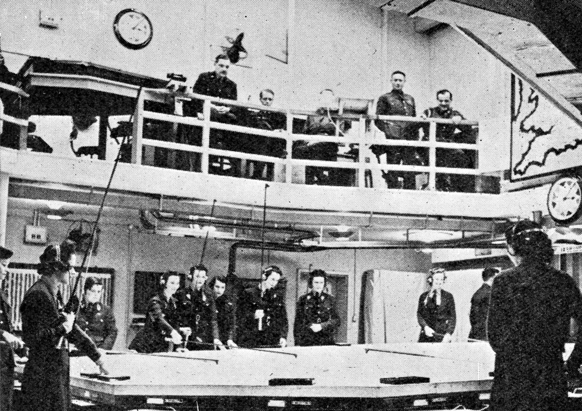
OPERATIONS ROOM AT FIGHTER COMMAND
Fig. 3.
Here information gleaned from the various reporting systems is plotted
on the large scale map on the centre table. The controller, seated in
the gallery, overlooks the map and by means of radio telephone he is
able to guide fighters into visual contact with the enemy
STATE OF READINESS
Round
the room are indicators showing the number of aircraft available for
operations, and the “state of readiness” of squadrons. A word of
explanation is perhaps necessary here. Squadrons must have their rest
periods sometime in the twenty-four hours, and to provide for these and
at the same time to allow for sufficient aircraft with crews to be
available for operations, a system has been adopted in which the
following abbreviations are used: “Released” means that a squadron is
off duty till a certain time; “Available,” that a squadron is ready to
come to stand-by at short notice; “Readiness,” that a squadron is able
to come to stand-by in about five minutes, though in practice it often
happens that a squadron in readiness is ordered to take off
immediately; and “Stand-by,” that a squadron is able to take off
within the shortest possible time.
At the controller’s side is a
microphone, by means of which he can talk to the fighter squadrons,
whether on the ground or in the air. Also there are telephones to
headquarters as well as to adjoining groups and stations. In most
operations rooms there will also be found liaison officers whose duty it
is to keep the anti-aircraft defences accurately and quickly informed
of the movements of both enemy and friendly aircraft, of the height of
balloon barrages.
PLOTTING A RAID
Let
us imagine ourselves to be actual onlookers standing beside the
controller at a fighter station, when suddenly one of the telephonists
near the map slides a small frame containing counters of various
colours with numbers on each, to a particular part of the map. If we
were in one of the more senior headquarters action would be taken
on this to give certain districts an air raid warning. We at a fighter
station, however, are engrossed with the fact that this is a daylight
raid approaching the area for whose defence the station is responsible.
A
glance at the squadron state of readiness board shows the controller
which squadrons are most readily available, and he at once warns them
to stand by, or even to take off immediately, thus allowing them to
climb towards the incoming enemy. The enemy’s height is shown on the
operations table, and a quick calculation into which wind speeds,
distances, speed and rate of climb of our fighters enter, shows when and
where interception is likely to occur.
The squadron in the most
advanced state of readiness already has its aeroplanes to the leeward
side of the aerodrome, ready to take off into wind, with engines
warmed up at regular intervals—depending on the time of year. The
pilots are near their machines, resting in shelters, with flying kit on,
ready to leap aboard their aircraft at a second’s notice.
Now
our fighters are off the ground and climbing hard. Information is sent
to the fighter leader by radio telephone from the operations room
telling him of the enemy’s movements, the movements of other fighter
squadrons, and the course to fly to intercept the enemy. The fighter
leader controls his formation by radio telephone and it is thus
possible to plot his position by direction-finding wireless, and, at the
same time, to indicate his course also, from moment to moment, on the
operations room map.
The draughtsman is busy transferring
information from the main map to his tracing; the anti-aircraft oflicers
are telephoning to their batteries; and other squadrons are being
brought to stand-by in case it is necessary to reinforce those already
in the air. Soon other raids begin to reveal their nearness on the map.
We see that the original raid has suddenly turned back towards Northern
France before it penetrated inland. It was only a small raid of, say,
three aircraft, but coming in now from another direction the counters
indicate a formation of at least thirty-six. Here is something for our
fighters to get their teeth into, and the controller decides to leave
the small formation alone, and to concentrate on the larger one. From
the times of their previously plotted positions the speed of the larger
formation can be estimated and another quick calculation by the
controller gives him the course which his fighters should steer to
intercept.
Every one’s attention is now riveted on the counters
on the table. It is like a race game played on a dining-room table. The
enemy counters alter course, another lightning calculation and the
controller’s voice gives the fighter leader another change of course.
The counters indicating our fighters get close to the enemy—surely they
must be in sight by now—no, a glance at the weather board shows
scattered cloud. The fighter leader reports that he has been joined by a
second, and yet a third squadron. The controller sighs in relief; he
has been able to concentrate a superior force of fighters at the right
time, place and height to meet the enemy. At last “enemy sighted” comes
through and then a set of crisp, simple orders from the fighter leaders
to their flight and section leaders. A wealth of experience,
knowledge of his pilots, tactics, lightning appreciation of the
enemy’s position and his own, and positions of the sun and clouds
influence these orders. After the fight the leaders inform their units
and are given courses to steer to bring them back to their home
aerodromes.
SOUND LOCATORS
If
we were to pay a visit to a typical searchlight position we would see a
curious device mounted on a four-wheeled trailer with a couple of men
operating it. It is a sound locator, and consists of a number of
sound-reflecting elements like very large motor car headlight reflectors
mounted so as to swing up and down and also round in a circle, so that
it can be aimed at any point in the heavens. Sound waves entering a
locator are reflected from the inner surfaces and become concentrated at
a point in the centre of the back of the device, whence they are drawn
off by telephones placed on the heads of the operators.
ELEMENTS OF A SOUND LOCATOR
Fig. 4.
The instrument swings round a point X. One man listens out on mirrors A
and B and swings the locator round until he gets maximum sound. A
second man operates mirrors C and D and swings them up and down
The
elements of a locator are grouped as shown in Fig. 4. The device swings
round the point X. One man listens out on A and B mirrors and swings
the instrument round till he gets the sound loudest in A and B. As he
is listening to the engine of a rapidly moving aircraft he may have to
keep moving the arm A—B round continually to keep the sound loud in his
telephones, so that he follows the course of the aircraft by its sound.
A
second man operates the mirrors C and D and swings them up and down. It
is clear then that by reading off the positions on scales to which the
locator is pointing the direction of an aircraft in the sky can be
ascertained. By calculating where this direction line crosses that from
another locator which is aimed at the same aircraft, its actual
position may be known.
High performance of modern aircraft has
rendered the operation of sound locators increasingly diflicult. With
radiolocation, however, the directing of searchlights and anti-aircraft
gunfire is becoming increasingly quick and accurate.
Consider an
aircraft at 20,000 feet approaching at a speed of 240 miles per hour.
From 20,000 feet sound takes about seventeen seconds to reach the
ground and as in that time the aircraft has travelled forward 1,994
yards, or a little over a mile it follows that the sound locator will
be directed at a point that distance behind the aeroplane. This, of
course, has to be allowed for in giving directions to searchlights or
guns (Fig. 5).
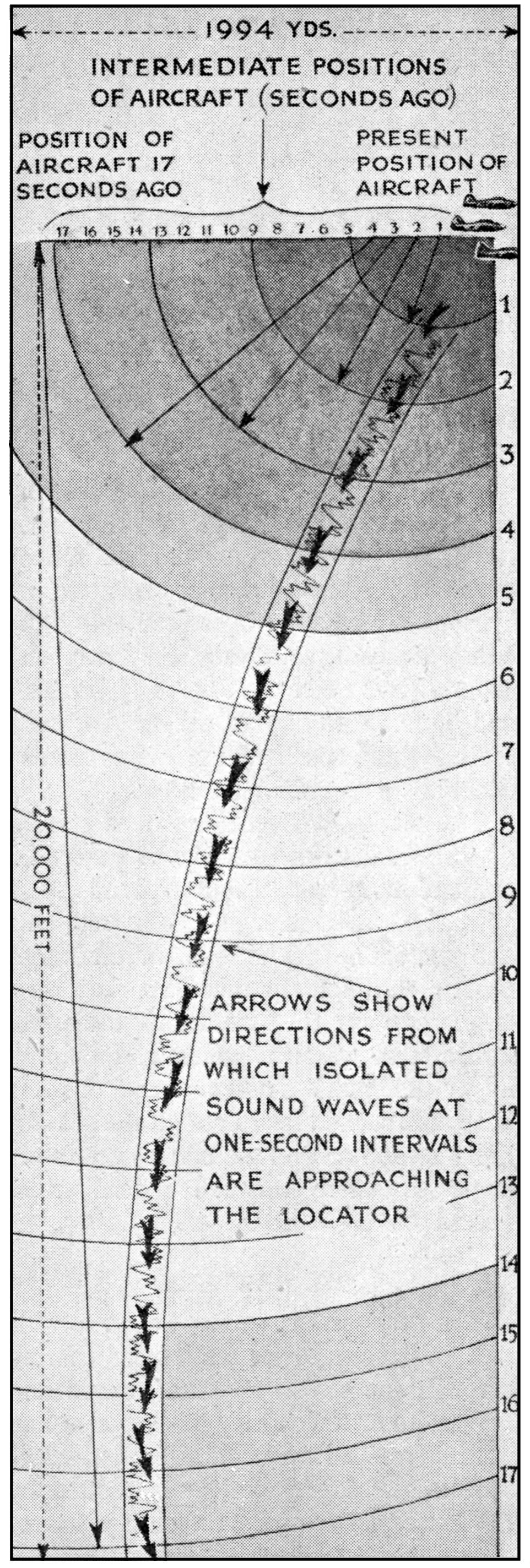
Fig. 5. Diagram of time lag of sound
SEARCHLIGHTS
Few
people in England are unfamiliar with the appearance of searchlight
beams. The light is produced by means of what is known as an electric
arc-lamp, which, briefly, has the advantage of producing a brilliant
centre of light. Instead of being dissipated in all directions this
light is concentrated by means of an optically designed reflector and
shot into the sky as a single beam from a source of some millions of
candle-power. Searchlights are nearly all mobile and, with their
self-contained generating sets, can be quickly moved from place to
place.
The searchlights can be turned round and brought up and
down so that the beam can be directed at any point in the sky. The
scales on the two axes of the light are marked in degrees as are those
on the sound locator, so that any readings on one can rapidly be
applied to the other. The sound locator operator simply passes his
readings, corrected to allow for enemy speed, to the searchlight crews,
who set the information on their scales and switch on. If all goes well
the beam immediately illuminates the aircraft.
This simple
explanation may perhaps make it clear as to how the problem of sound
location increases when the sky is full of aircraft, making it very
difficult for the operators to keep track of any one individual
aeroplane. There are also the various interruptions caused by
anti-aircraft barrage, high winds, and any local noises near the
sound locator.
The antidote to the searchlight from the bomber’s
point of view is to paint the raiding aircraft with black, lustreless
paint, to shroud the engine exhaust system so that no red hot pipes or
flames are visible and to cut down the cockpit and interior lighting to
the bare minimum necessary for navigation and flying. The light likely
to be shown by or reflected from a bomber is thus reduced to something
very small indeed. Night glasses may assist in distinguishing it,
however, and, again, searchlights may illuminate the enemy sufficiently
to enable one of our night fighters to identify and attack it. Various
attempts to overcome this difficulty of seeing our bombers from the
ground have been tried by the Germans, and light blue, pink, orange and
red searchlights have been seen on various occasions over enemy
territory.
The actual A.A. gun positions consist of well
camouflaged and well protected emplacements spaced some distance apart
with attendant range finders, a predictor and telephones. There is an
officer in charge who plots the incoming raids on a large map on the
operations table, on information which is continually coming in by
telephone. When enemy raiders have approached near enough the
searchlights switch on and the battery observers begin to watch through
special night glasses for signs of the enemy.
A.A. BATTERY
The
problem the battery has to solve is that of trying to hit an object
roaring through the air on a course, speed and height, all of which may
be altered at any moment at the whim of the pilot, so as soon as the
enemy aircraft is sighted by the battery, the officer in charge has to
utilize what information he has, or can obtain, as to course, speed and
height in order to calculate the point in space at which to fire his
guns, so that the shell and the aircraft shall, if possible, arrive at
that point simultaneously. One can no more than assume that the enemy
will follow a particular course. If he is not being fired on, or if he
is approaching an important objective, however, it is probable that he
will continue at constant speed on a straight and level course.
FLIGHT OF SHELL
There
is then the flight of the shell to consider. It naturally takes time to
reach the place where it is designed to meet the aircraft, and during
its flight it is subject to effects of wind and temperature. On the
assessment of these factors depends the fuse setting, which determines
the time between the firing and the bursting of the shell. If all the
multitudinous calculations thus involved had to be done without some
quick mechanical means, the aircraft would be well out of range before
the gun could be fired. The predictor delivers the answer not only at
once, but also continuously while it is directed on the enemy.
CONSTRUCTION OF A BARRAGE BALLOON
Fig. 6.
Diagram of principal parts of a barrage balloon. It is filled with
hydrogen, and is designed so that if there is a wind extra lift is
obtained, the balloon acting as a kite. The mooring cable is attached
to the balloon by means of twelve flying wires (see also Fig. 7)
BARRAGE BALLOONS
Balloon
barrages also play an important part in protecting important objectives
on land and even out at sea. The balloons are made of special fabric
and are filled with hydrogen gas which, being lighter than air, causes
the balloon when inflated to rise, drawing with it the mooring cable. It
is this cable which constitutes the danger to aircraft. Contact with it
is almost certain to damage the aeroplane sufficiently to bring it
down, either crashing or in a forced landing (Figs. 6 and 7).
The
balloon is so designed that if there is a wind, increased lift is
obtained, the balloon acting as a kite. It is therefore possible to fly
a barrage at greater heights on reasonably windy than on calm days.
Captive
balloons are prone to other weather effects such as thunderstorms, when
they may act as excellent lightning conductors. If struck by
lightning, the balloon is usually set on fire and becomes a total loss.
Snow may freeze on the top surface of the balloon and reduce
performance owing to the increased weight.
To
a casual observer it might appear that owing to the spaces between the
balloons in the barrages, there would be plenty of room for aircraft to
turn so as to avoid coming in contact with the cables. It is true that
on days when there is no cloud, the balloons may be visible to an enemy
pilot and he might dive into the barrage to launch his attack, but once
within the barrage he might find it extremely difficult to avoid the not
easily discernible balloon cables as turns at high speed with fast
modern monoplanes cannot be carried out in a small space.
But
on days when there is a layer of cloud, the balloons will not be
visible and it would be a foolhardy act indeed to fly into the barrage
area, for it would be impossible to see the balloon cables until too
late to avoid them. In these conditions, or at night, it is the
knowledge that the balloon barrage exists at a given locality that
prevents the pilot going down so that he can sight his target on the
ground. In other words, the barrage has affected the pilot’s morale.
This
brings us to the second reason for the barrage, and that is to prevent
the enemy coming lower than a given height—that is, the top of the
barrage. Thus low flying attacks on targets such as cities and war
factories are prevented.
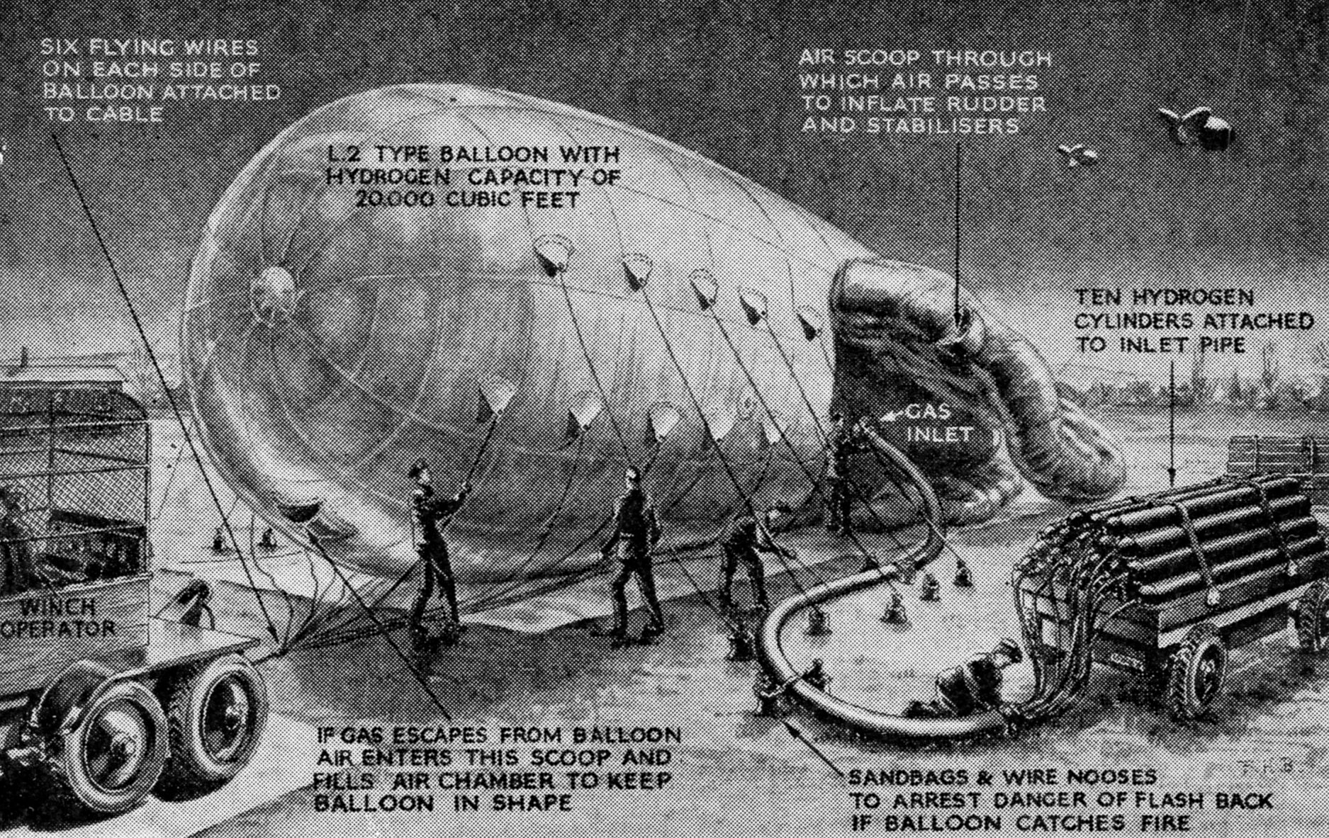
INFLATING A BARRAGE BALLOON
Fig. 7.
Diagram showing how a barrage balloon is inflated with hydrogen. The
rudder and stabilizers are not filled with hydrogen, but with air only
by means of air scoops, and air also enters the scoop in front to keep
the balloon in shape should any leakage of gas occur
The maximum height to which the barrage
can be raised cannot, of course, be divulged, but the greater the
height, the greater the weight of cable which has to be lifted. All
sorts of tricks can be played with it to outwit and mislead the enemy,
such as placing balloons at varying heights, moving balloons up and
down during the alert periods, and changing the concentration of
balloons.
The enemy has tried out many devices to overcome the
danger of hitting balloon cables. One idea which the Germans
experimented with was a device to fend off the balloon cable. It was
fixed as shown in Fig. 8, but detracted considerably from the aircraft’s
performance. Britain had also experimented with various cutting devices
on the leading edge of the aircraft’s planes.
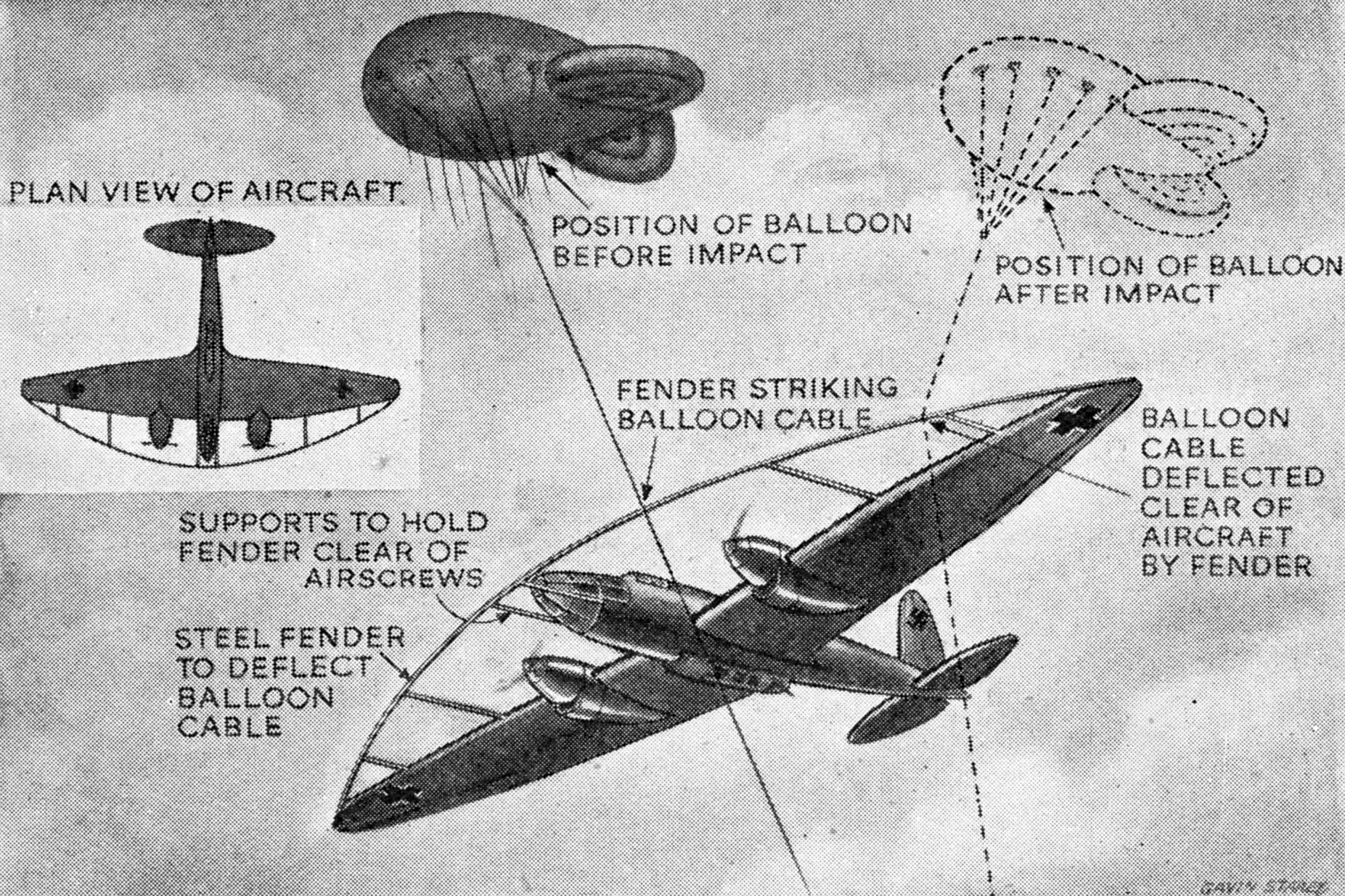
DEVICE TO BEAT THE BALLOON
Fig. 8.
Diagram illustrating device tried by the Germans to overcome the danger
of hitting a balloon cable. Its object was to push the cable clear of
the aircraft, but it had the disadvantage of considerably reducing the
bomber’s performance. Some Allied aircraft have been fitted with devices
to beat the balloon, but it is probable that they also reduce the
aircraft’s efficiency
INSIDE A BOMB STORE
The
R.A.F. keep their bombs safely stored away underground. When they are
required they are loaded into trolleys and hauled to the aircraft. The
men seen above are getting a consignment of 500-lb. bombs out of store
ready for a big raid on objectives in Germany
The weapons of
attack used by aircraft consist of bombs, torpedoes, mines, and
fire with shell-firing guns and machine guns. Bombs have high
explosive or incendiary fillings. The high explosive bomb consists of
metal body filled with explosive. The effect is designed to be produced
either by disruptive effect of blast, which is caused by the sudden
release of a large quantity of gases under high pressure when explosion
occurs, or through the damage caused by fragments.
BRITAIN’S BIG BOMBS
The
blast of a bomb has most effect in a confined space, and thus it is
essential for the bomb to penetrate well into the target if maximum
disruptive effect is desired. Britain has produced the largest and most
effective bomb yet used in this war. It weighs 8,000 1b., is about
seven and a half feet long and two and a half feet in diameter. No open
space could be found in Britain for testing it, so widespread is
the effect of its blast.
Let us consider for a moment the types
of high explosive bombs now in use. First of all we have anti-personnel
bombs designed to break up when the explosion occurs into the greatest
possible number of fragments big enough to produce casualties over
a large area. Then there are “general purpose” bombs, which strike a
balance between blast and fragment effect. These bombs are not designed
to stand up to being dropped on very hard targets, such as the armoured
deck of a battleship, and for this purpose we have semi-armour piercing
and armour piercing bombs.
The first of these have heavy bodies
which disintegrate into large fragments. They can penetrate light
armour plate and multi-storied buildings, and can be relied upon to
reach their maximum depth of penetration into the target without
breaking up. The armour piercer is, of course, designed to penetrate
well into heavily armoured vessels when dropped from a great enough
height.
ANTI-SUBMARINE AND INCENDIARY BOMBS
Among
other recent types are the special bombs which have been produced
for use against submarines. They contain large charges of high
explosive, and, like the depth charge, give an intense pressure wave in
water which will cause the hull of a submarine to leak if the explosion
is close enough to it.
Incendiary bombs usually depend on
phosphorus or magnesium compounds suitably ignited for their effect.
They are of various sizes and for convenience are carried in special
containers fitted to the bomb cells of the aeroplane, from which they
can be scattered over large areas. There are also gas bombs which
consist of easily breakable containers filled with gas in liquid form.
It was always laid down that poison gas would never be dropped by the
R.A.F. unless the enemy first made use of it against us.
BOMB FUSES
Now
a word as to the fusing of bombs. The fuse is a device by which the
explosive charge in the bomb is made to explode. The explosion may be
desired instantaneously when the bomb hits the ground, or after very
short intervals of time from small fractions of a second up to several
seconds or after long periods, running into days or even weeks. The
fuses are fitted either in the nose or tail of the bomb, sometimes in
both places, depending on the type of bomb. Nose fusing is usually
chosen for instantaneous action and tail fusing for delay functioning.
Experiments carried out against specially constructed targets, and
results of experience in operations help the Air Staff to decide on the
type of bomb and fusing best suited to the particular type of target to
be attacked.
Magnetic mines dropped from aircraft do not have
cables and sinkers, or anchors attached to them; they remain lying on
the bottom of the sea in which they are dropped. They have to be
rendered insensitive to the impact of the water when dropped, but
to become extremely sensitive afterwards. The dropping of ordinary
mines from the air is illustrated here.
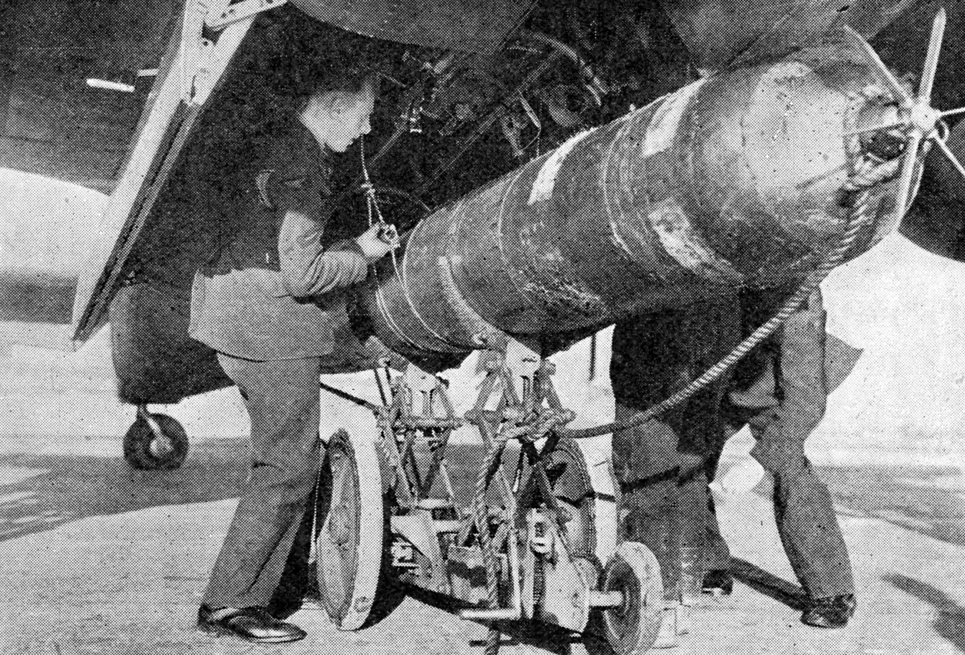
LOADING A BEAUFORT TORPEDO BOMBER
Torpedoes
dropped from the air are very similar to those used by ships, but are
slightly more robust so as to stand up to the impact of being dropped
into the sea by fast-flying aircraft. Above, an aircraft torpedo is seen
being loaded into the bomb cell of a Bristol Beaufort
TORPEDOES
Another
weapon which is used by aircraft is the torpedo. Perhaps of all air
weapons the torpedo has proved the most startlingly effective in this
war. The most striking examples were afforded by the attacks on the
Italian fleet at Taranto and Matapan, the disablement of the Bismarck, and the sinking of the Prince of Wales and Repulse by the Japanese.
The
torpedo dropped by aircraft is very similar to the ship’s torpedo; it
is slightly more robust as it has to stand being dropped into the sea
from an aircraft perhaps flying at 250 miles per hour at a low height of
up to 150 feet. It runs a distance considerably shorter than the ship’s
torpedo, at a speed of up to forty-five land miles per hour. Its use is
a tremendous test of the courage of the crew of the aircraft as release
has to be close to the target. The dropping aircraft has to take rapid
evasive action after releasing the torpedo so as to avoid the heavy
concentration of fire from the ship’s guns.
Qualified pilots of
the Fleet Air Arm undergo a course of intensive training in the
technique of torpedo attack at the Royal Naval Air-Torpedo School
somewhere along the coasts of Britain. All their training is carried
out under actual battle conditions, and attacks on the target practice
ship are made with real torpedoes fitted with dummy heads. These torpedo
heads contain a buoyant apparatus so that the torpedoes can rise to the
surface after running their course.
ACKNOWLEDGMENTS
The
editor has received the welcome co-operation of numerous periodicals and firms who have given him permission to reproduce
photographs and drawings. He takes this opportunity of expressing
his gratitude for their help. Below is given a list of the
contributors.
The Aeroplane
Flight
Illustrated London News
Life
The Sphere
Henry Hughes & Son
Phillips & Powis
Messrs. Spink & Son
Vickers-Armstrongs, Ltd.